background image

Fitting the Combined Systems - 2Point Occupant Restraint   

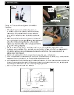
1.  Ensure the Comfort Clip is released (Fig 15) and press the buckle to  

release the lap belt. 

2.  Pull the metal tongue on the black webbing upwards to release the  

webbing from both inertia reels. 

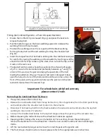
3.  Position the webbing across the occupant with the black webbing  

forming the lap belt and the red webbing forming the shoulder belt  
(Fig 16).  

4.  Insert the tongue fixed to the black webbing into the stalk buckle. Adjust 

for comfort by raising the webbing on the shoulder by two finger widths, 
unlock the Comfort Clip to take up the slack, then re-lock the clip so that 
it rests on the reel cover. 

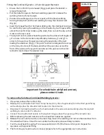
5. 

The lap belt anchor points should be positioned to achieve belt angles of 
30° or more to the horizontal and preferably between 45° and 75° in  
order to fit low across the pelvis reducing the possibility of the belt  
loading the abdomen (Fig 17). The pelvic restraint is designed to bear up-
on the bony structure of the body and should be worn low across the 
front of the pelvis with any junctions between the pelvic and shoulder 
restraints located near the wearers hips. 


To remove the Combined Rear Tie-Down: 


1. 

If required, release the Comfort Clip.


2.  Release the red shoulder belt from the lap belt section, then if applicable, from the third point fixing 

and carefully allow the shoulder belt to return to the retractor.  

3.  Disconnect the black lap belt from the buckle stalk on the aisle side and carefully allow the lap belt 

webbing to return onto it’s retractor. 

4.  Connect the shoulder belt buckle to the lap belt tongue above the opening of the retractor box. 

5.  Before releasing the restraint ensure the wheelchair brakes are applied.  
6.  Keeping control, release the over-centre buckle on the rear strap, loosen the webbing and remove the 

karabiner or tongue & buckle fixings from the wheelchair frame. Close the over-centre buckle and  
return webbing to Velcro.  

7.  Lift the rear restraint plunger and remove from rail. Repeat operation with opposite fitting. 
8.  The front straps should now be removed, please refer to the appropriate user instructions. 

Comfort Clip 

15

16 

17 

Содержание OR01

Страница 1: ...s manual for future reference Please include it with the product in the event of transfer to new users Additional copies are available upon request Unwin House The Horseshoe Coat Road Martock Somerset...

Страница 2: ...ns 6 The development of Unwin wheelchair tie downs and occupant restraints is a continuous process Applications are added on a regular basis For more detail contact Unwin or look on the Unwin website...

Страница 3: ...er belt anchorage must be roof or side wall anchored at a height level such that the belt webbing passes over the midpoint of the occupant shoulder and at a height that is at or just above the level o...

Страница 4: ...3 and push firmly down and towards the wheelchair until the yellow plunger drops and locks into the rail Ensure that each ATF is sited opposite each other 4 Remove the webbing from the Velcro patch a...

Страница 5: ...ate an angle of about 30 45 within the rear view zone Fig 5 Some chairs will indicate this tie down position 8 Pull the webbing through the over centre buckle until it is tight With the free hand begi...

Страница 6: ...the wheelchair main frame to create an angle of about 30 45 within the rear view zone Fig 11 Some chairs will indicate this tie down position If using tongue and buckle press the red buckle button s...

Страница 7: ...t is vertically above the inertia reel casing fixed onto the floor fixing Unfasten the tongue and buckle 2 Pull the black webbing upwards and unfasten the tongue from the red webbing buckle 3 Position...

Страница 8: ...the body and should be worn low across the front of the pelvis with any junctions between the pelvic and shoulder restraints located near the wearers hips To remove the Combined RearTie Down 1 If req...

Страница 9: ...rd or backward until the plunger drops and locks into place Fig 18 Repeat with other bar IMPORTANT Check that both bars are positioned exactly opposite each other they are secured and the plungers are...

Страница 10: ...it is vertically above the inertia reel casing fixed onto the floor fixing Unfasten the tongue and buckle 2 Pull the black webbing upwards and unfasten the tongue from the red webbing buckle 3 Positio...

Страница 11: ...nd should be worn low across the front of the pelvis with any junctions between the pelvic and shoulder restraints located near the wearers hips Important For wheelchairs with fixed armrest please con...

Страница 12: ...ome raising the anchor from its housing if using the retractable Solar floor anchor and rotate the cleat through 90 Fig 29 to align the karabiner with the wheelchair frame Install the second rear tie...

Страница 13: ...t is vertically above the inertia reel casing fixed onto the floor fixing Unfasten the tongue and buckle 2 Pull the black webbing upwards and unfasten the tongue from the red webbing buckle 3 Position...

Страница 14: ...ss the front of the pelvis with any junctions between the pelvic and shoulder restraints located near the wearers hips Important For wheelchairs with fixed armrest please contact Unwin To remove the S...

Страница 15: ...them immediately 3 All webbing and components can be cleaned as necessary but care should be taken to prevent contamination of the webbing with polish oils and chemicals particularly acid alkalis and...

Страница 16: ...Unwin House The Horseshoe Coat Road Martock Somerset TA12 6EY UK Tel 44 0 1935 827740 Fax 44 0 1935 827760 Email sales unwinsafety com Website www unwinsafety com...

Отзывы: