P a g e
| 14
Steel Body, Automatic Wood Pellet Feed Hot Water Boiler Operation and Maintenance
Manual
1. Control panel
7. Circulation pump
13. Lid for additional feeding
2. Control card box
8. Fan
14. Ventilation
3. Rotary gearbox
9. Flue
15. On/Off switch
4. Feeding gearbox
10. Cleaning arm
16. Flow line
5. Closed expansion tank
11. Ash removal cover
17. Return line
6. Safety valve
12. Servicing cover
18. Filling/discharging
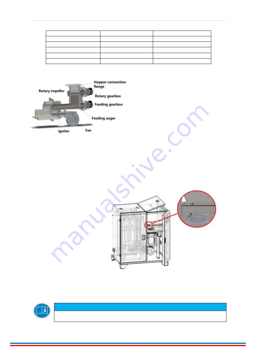
Gearboxes, fan, rotary impeller, auger and
ignitor group is called burner group. This group
can be reached by opening the boiler service
door. Children and unauthorized personnel
should not be allowed to reach this group.
Manometer can be seen when the left front
door of the boiler is opened. Water pressure can be observed from the manometer while adding
water.
When the left front door of the boiler is opened, a safety thermostat slot can be seen on the card box
with the title Ünmak.
When the boiler goes to high
temperature, it gives an excessive
heat error, stops the fuel supply and
fan blow. When the temperature in
the boiler decreases, the plastic cover
on the safety thermostat is removed
and the boiler is reactivated by
pressing the red pin inside. It will not
let you press if the water temperature
in the boiler is not low enough.
ATTENTION
You do not need to open the card box to press the pin of the safety thermostat. You can loosen
the plastic bolt of the thermostat by removing it.


