— 16 —
Printer
Pin
Signal
2
TXD
3
RXD
4
RTS
6
DSR
7
SG
20
DTR
PC
Signal
Pin
FG
1
TXD
2
RXD
3
CTS
5
DSR
6
SG
7
DTR
20
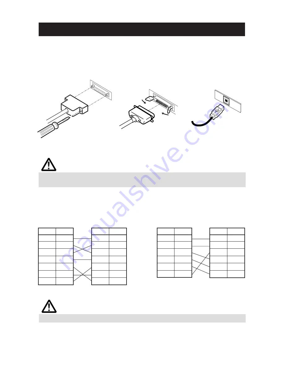
3.2 Connecting Interface Cables
Confirm that the power switch is OFF and connect the interface cable.
Orient the interface cable terminal correctly and insert it into the interface
connector.
CAUTION!
■
When disconnecting the cable, always hold the connector.
■
Be careful not to insert the USB interface cable into the cash drawer kick-out connector.
Serial Interface
Parallel Interface
For serial interface cable, use the one with the following connection.
25-pin - 25-pin cable
9-pin - 25-pin cable
Printer
Pin
Signal
1
FG
2
TXD
3
RXD
4
RTS
6
DSR
7
SG
20
DTR
PC
Signal
Pin
RXD
2
TXD
3
DTR
4
SG
5
DSR
6
CTS
8
USB Interface
CAUTION!
Avoid locating the interface cable in places which may cause tripping or falling.


