Universal Robots UR-6-85-5-A Скачать руководство пользователя страница 45

3.3. Robot Control

Screen layout

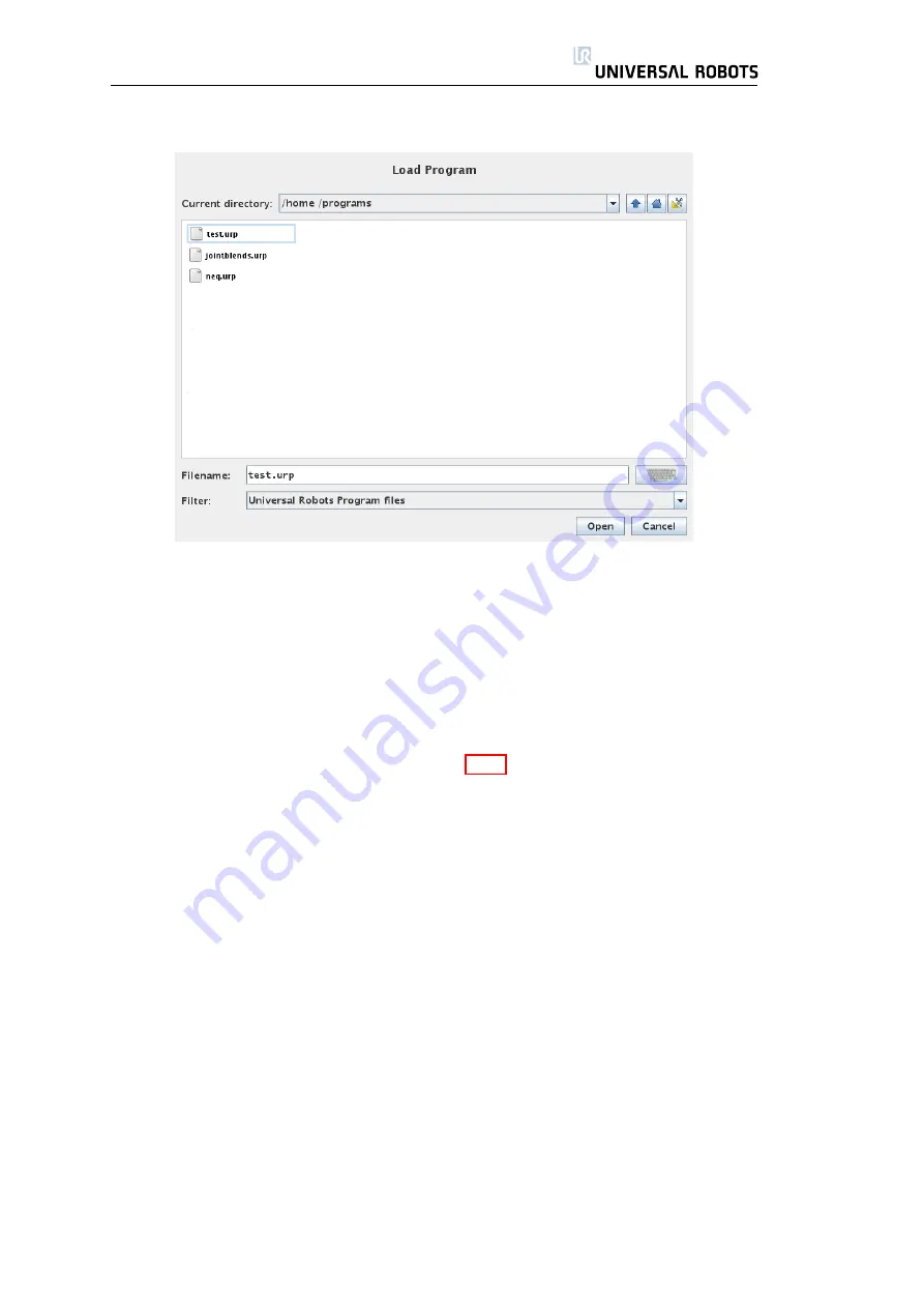
This image shows the actual load screen. It consists of the following important

areas and buttons.

Path history

The path history shows a list of the paths leading up to the present

location. This means that all parent directories up to the root of the computer
are shown. Here you must notice that you may not be able to access all the
directories above the programs folder.

By selecting a folder name in the list, the load dialog changes to that direc-

tory and displays it in the file selection area 3.3.7.

File selection area

In this area of the dialog the contents of the actual area is

present. It gives the user the option to select a file by single clicking on its name
or to open the file by double clicking on its name.

In the case that the user double-clicks on a directory, the dialog descends

into this folder and presents its contents.

File filter

By using the file filter, one can limit the files shown to include the type

of files that one wishes. By selecting “Backup Files” the file selection area will
display the latest 10 saved versions of each program, where

.old0

is the newest

and

.old9

is the oldest.

File field

Here the currently selected file is shown. The user has the option to

manually enter the file name of a file by clicking on the keyboard icon to the
right of the field. This will cause an on-screen keyboard to pop up where the
user can enter the file name directly on the screen.

Open button

Clicking on the Open button, will open the currently selected file

and return to the previous screen.

45

UR-6-85-5-A

Содержание UR-6-85-5-A

Страница 1: ...UR 6 85 5 A User Manual Version 1 11 January 2010...

Страница 2: ...2 UR 6 85 5 A...

Страница 3: ...troller Box 15 1 4 5 Mounting the Touch Panel 15 1 4 6 Connecting the Robot Cable 15 1 4 7 Connecting the Mains Cable 15 2 Electrical Interface 17 2 1 Introduction 17 2 2 The Emergency Stop Interface...

Страница 4: ...point 52 3 4 8 Program Command Tab Wait 53 3 4 9 Program Command Tab Action 53 3 4 10 Program Command Tab Popup 54 3 4 11 Program Command Tab Halt 54 3 4 12 Program Command Tab Comment 55 3 4 13 Progr...

Страница 5: ...2 3 Description and Identification of Product 74 4 2 4 Essential Requirements 74 4 2 5 National Authority Contact Information 75 4 2 6 Important Notice 76 4 2 7 Place and Date of the Declaration 76 4...

Страница 6: ...Contents 6 UR 6 85 5 A...

Страница 7: ...s easy to program the robot to move the tool along a desired trajectory PolyScope is described in section 3 1 The reader of this manual is expected to be technically minded to be fa miliar with the ba...

Страница 8: ...e given using a series of waypoints Each waypoint is a point in the robot s workspace Waypoints A waypoint is a point in the workspace of the robot A waypoint can be given by moving the robot to a cer...

Страница 9: ...d Turning the robot on is done at the initial ization screen by touching the ON button at the screen When it is turned on a noise can be heard as the brakes unlock After the robot has been turned on i...

Страница 10: ...t s file system which may result in a robot malfunction However if the system locks up you can force a shutdown by pushing and holding the On button at the front side of the controller box for five se...

Страница 11: ...ed in the tree structure on the left side of the screen 17 Go to the Structure tab 18 Touch the Move button 19 Go to the Command tab 20 Press the Next button to go to the Waypoint settings 21 Press th...

Страница 12: ...5 5 A robot extends to 850 mm from the base joint The workspace of the robot is shown in figure 1 2 It is important to consider the cylindrical volume directly above and directly below the robot base...

Страница 13: ...132 0 5 Outer diameter of robot 0 05mm mounting flange Surface on which the robot is fitted It should be flat within Cable exit 2 0 010 8 0 015 149 M8 12 4 8 5 OR Figure 1 3 Holes for mounting the rob...

Страница 14: ...1 4 Mounting Instructions Figure 1 4 The tool output flange EN ISO 9409 1 A50 This is where the tool is mounted at the tip of the robot All measures are in mm 14 UR 6 85 5 A...

Страница 15: ...nnector at the button of the controller box Ensure that the connector is properly locked Connecting and disconnecting the robot cable may only be done when the robot power is turned off which is easil...

Страница 16: ...1 4 Mounting Instructions 16 UR 6 85 5 A...

Страница 17: ...tions explain how to use the electrical I O Note that according to the IEC 61000 standard cables going from the controller box to other machinery and factory equipment may not be longer than 30m unles...

Страница 18: ...e understanding of the emergency circuitry and the owner of the ma chinery takes full responsibility for connecting it correctly and to the right safety level Note the number of safety components that...

Страница 19: ...fety level If this rule is not followed it is not possible to get a high safety level because one failure in normal I O can prevent an emergency stop signal from resulting in an emer gency stop Other...

Страница 20: ...s used together with other electro mechanical machinery it is often required to set up a common emergency circuit This ensures that if a dangerous situation arises the operator does not need to think...

Страница 21: ...a similar device that can give a signal when a person is near the robot When paused the program can be resumed without loss of program state To resume the program click Continue on the Popup on the sc...

Страница 22: ...ctionality seems to be present Never combine the emergency stop circuit with the normal I O The abbreviations of the I O panel are explained in table 2 3 24V 24V power supply GND 0V GND connection DOx...

Страница 23: ...O and that the maximum of 800mA is for both power sources together The internal control system will power off the robot if the current exceeds its limit This will also generate an error message in the...

Страница 24: ...d off Load Controlled by Digital Output External Power If the available current from the internal power supply is not enough or if the load needs another voltage such as 12V simply use an external pow...

Страница 25: ...ustration shows how to connect a button using an external power source Remember that table 2 6 specifies the valid supply voltage for this case Signal Communication with other Machinery or PLCs If com...

Страница 26: ...th current mode and voltage mode in the range of 4 20mA and 0 5V respectively The analog outputs are limited by the data shown in table 2 7 To illustrate clearly how easy it is to use analog outputs s...

Страница 27: ...ich are im plemented in different ways and therefore can have different offset and gain errors The technical data defining limitations on the analog inputs are shown in table 2 8 The specified differe...

Страница 28: ...and the ohmic change due to tempera ture must be added to the error specifications of the analog inputs Using Analog Inputs Non differential Current Input If the output of the equipment is a non diff...

Страница 29: ...nected to GND same as the red wire The available power supply can be set to either 0V 12V or 24V at the I O tab in the graphical user interface see section 3 3 2 Take care when using 12V since an erro...

Страница 30: ...ne the output voltage at the I O tab see section 3 3 2 Keep in mind that there is voltage between the POWER connection and the shield ground even when the load is turned off 2 5 2 Digital Inputs The d...

Страница 31: ...have current mode functionality which is an advantage compared with the controller I O The analog inputs can be set to different input ranges which are implemented in different ways and therefore can...

Страница 32: ...uts Differential Using sensors with differential outputs is also straightforward Simply connect the negative output part to GND 0V with a terminal strip and it will work in the same way as a non diffe...

Страница 33: ...Chapter 3 PolyScope Software 33...

Страница 34: ...ged in tabs for easy access on the screens In this example the Program tab is selected at the top level and under that the Structure tab is selected The Program tab holds information related to the cu...

Страница 35: ...This is the simplest way to op erate the robot but requires a suitable program to have already been produced Program Robot Change a program or create a new program Setup Set passwords upgrade software...

Страница 36: ...he robot to operate normally Auto movement Auto Buttons Normally it is always advisable to use the auto buttons to move the individual joints until they reach a known state In order to operate the but...

Страница 37: ...Simple number typing and editing facilities In many cases the unit of the typed value is displayed next to the number 3 2 2 On screen Keyboard Simple text typing and editing facilities The Shift key c...

Страница 38: ...les can be found in the Variable selector while the names of the input and output ports can be found in the Input and Output selectors Some special functions are found in Function The expression is ch...

Страница 39: ...a small green ball Note Release the button to stop the motion at any time Move Joints Allows the individual joints to be controlled directly Each joint can move from 360 to 360 which are the joint li...

Страница 40: ...ng program execution If anything is changed during program execution the program will stop At program stop all output signals will retain their states The screen is updated at only 10Hz so a very fast...

Страница 41: ...s the movement the robot is about to perform Compare the animation with the position of the real robot and make sure that robot can safely perform the movement without hitting any obstacles Auto Hold...

Страница 42: ...t is set correctly The default is that the robot is mounted on a flat table or floor in which case no change is needed on this screen However if the robot is ceiling mounted wall mounted or mounted at...

Страница 43: ...ve to the center of the tool output flange as indicated on the on screen graphics The two buttons on the bottom of the screen are relevant when the TCP is changed Change Motions recalculates all posit...

Страница 44: ...the message itself 3 3 7 Load Screen On this screen you choose which program to load There are two versions of this screen one that is to be used when you just want to load a program and execute it an...

Страница 45: ...le clicking on its name or to open the file by double clicking on its name In the case that the user double clicks on a directory the dialog descends into this folder and presents its contents File fi...

Страница 46: ...er Parent Move up in the directory structure The button will not be enabled in two cases when the current directory is the top directory or if the screen is in the limited mode and the current directo...

Страница 47: ...ogram need to be filled in 3 4 2 Program Tab The program tab shows the current program being edited The program tree on the left side of the screen displays the program as a list of commands while the...

Страница 48: ...n or running it on the real robot When running in simulation the robot does not move and thus cannot damage itself or any nearby equipment in collisions Use simulation to test programs if unsure about...

Страница 49: ...is moving and also whether the motion is in joint space or linear space In joint space each joint is controlled to reach the desired end location at the same time which results in a curved path for t...

Страница 50: ...d Blend radius If a blend radius is set the robot trajectory blends around the waypoint allowing the robot not to stop at the point Blends cannot overlap so it is not possible to set a blend radius th...

Страница 51: ...thick black line moves in straight lines outside the blend areas dashed circles while the tool trajectory deviates from the straight line path inside the blend areas Also notice that the state of the...

Страница 52: ...in this case calculated_pos The variable can be a list of joint angles in radians such as given by the assign ment var 0 1 0 4 0 2 2 0 2 1 3 14 or a pose such as var p 0 5 0 0 0 0 3 14 0 0 0 0 The fir...

Страница 53: ...r digital or analog outputs to a given value Can also be used to set the payload of the robot for example the weight that is picked up as a consequence of this action Adjusting the weight can be necce...

Страница 54: ...e can be selected and the text itself can be given using the on screen keyboard The robot waits for the user operator to press the OK button under the popup before continuing the program If the Halt p...

Страница 55: ...program This line of text does not do anything during program execution 3 4 13 Program Command Tab Folder A folder is used to organize and label specific parts of a program to clean up the program tr...

Страница 56: ...in number of times a dedicated loop variable called loop_1 in the screen shot above is created which can be used in expressions within the loop The loop variable counts from 0 to N 1 When looping usin...

Страница 57: ...ental changes to the SubProgram Program Command Tab Call SubProgram A call to a sub program will run the program lines in the sub program and then return to the following line 3 4 16 Program Command T...

Страница 58: ...valuated to True the lines inside this If are executed Each If can have several ElseIf and one Else command These can be added using the buttons on the screen An ElseIf command can be removed from the...

Страница 59: ...Tab Event An event can be used to monitor an input signal and perform some action or set a variable when that input signal goes high For example in the event that an output signal goes high the event...

Страница 60: ...e with the robot program with variables and output signals 3 4 21 Program Command Tab Pattern The Pattern command can be used to cycle through positions in the robots program The pattern command corre...

Страница 61: ...ular pattern the List option can be chosen where a list of all the positions is provided by the programmer This way any kind of arrangement of the positions can be realized Defining the Pattern When t...

Страница 62: ...the numbers from 0 to X Y Z 1 the number of points in the pattern This variable can be manipulated using assignments and can be used in expressions 3 4 22 Program Command Tab Pallet A pallet operatio...

Страница 63: ...foreStart The optional BeforeStart sequence is run just before the operation starts This can be used to wait for ready signals AfterEnd The optional AfterEnd sequence is run when the operation is fini...

Страница 64: ...uence The next time round the robot starts the search from the remembered position incremented by the item thickness along the direction The stacking is finished when the stack hight is more than some...

Страница 65: ...st points TCP to the second points TCP 1 Next Stacking Position Expression The robot moves along the direction vector while continuously evaluating whether the next stack position has been reached Whe...

Страница 66: ...3 4 Programming Pick Place Sequence Like for the Pallet operation 3 4 22 a special program sequence is performed at each stack position 66 UR 6 85 5 A...

Страница 67: ...rent position of the robot and the shadow of the robot shows how the robot intends to reach the waypoint selected in the left hand side of the screen The 3D view can be zoomed and rotated to get a bet...

Страница 68: ...and type you wish to insert For adjusting the details for the new command go to the Command tab Commands can be moved cloned deleted using the buttons in the edit frame If a command has sub commands a...

Страница 69: ...bot software to a newer version via the Internet see section 3 5 3 Set Password Provides the facility to lock the programming part of the robot to people without a password see section 3 5 4 Calibrate...

Страница 70: ...y each joint needs to move a little about 20 to finds its exact position The Auto button drives all joints until they are OK The joints change drive direction when the button is released and pressed a...

Страница 71: ...run without the password but a password is required to create or change programs 3 5 5 Setup Screen Calibrate Touch Screen Calibrating the touch screen Follow the on screen instructions to calibrate...

Страница 72: ...3 5 Setup 3 5 6 Setup Screen Network Panel for setting up the Ethernet network An Ethernet connection is not neces sary for the basic robot functions and is disabled by default 72 UR 6 85 5 A...

Страница 73: ...rranty Claims under the Warranty must be submitted within two months of the Warranty default becoming evident Ownership of de vices or components replaced by and returned to Universal Robots shall ves...

Страница 74: ...fer universal robots com 4 2 3 Description and Identification of Product The robot is intended for simple and safe handling tasks such as pick and place machine loading unloading assembly and palletiz...

Страница 75: ...ectives are primary directives A product can only be covered by one primary directive and because the main hazards of the robot are due to mechanical movement and not electrical shock it is covered by...

Страница 76: ...Machinery Directive 2006 42 EC and with national implementing legislation 4 2 7 Place and Date of the Declaration Place Universal Robots ApS Svendborgvej 102 5260 Odense S Denmark Date 29 December 200...

Страница 77: ...Appendix A Safety Assessment 77...

Страница 78: ...hould move at less than 250 mm sec that is 1 meter in 4 seconds In addition the max imum force exerted by the robot should be 150N and the mechanical power should be less than 80W The robot software h...

Страница 79: ...side the robot s trajectory but within reach of the robot There are two potential accidents in this installation 1 An error in the robot s program can cause it to reach out into the passage 2 A person...

Страница 80: ...so possible that the person realizes his mistake and avoids the accident so av 3 The sum is 11 This accident will result in a bruise that can be treated by first aid so the risk assessment class is D...

Отзывы: