6
RHT
Series
2.0
Installation
2.0
Installation
• Electrical Requirements
WARNING
!
!
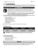
Improper installation, adjustment, alteration, service or maintenance can cause property
damage, serious injury or death. Read and understand, the installation, operating and
maintenance instructions thoroughly before installing or servicing this equipment. Only
trained, qualified gas installation and service personnel may install or service this equipment.
Not for residential use!
Do not use this heater in the home, sleeping quarters, attached
garages, etc.
Installation of a commercial tube heater system in residential indoor
spaces may result in property damage, serious injury or death.
NOTICE
• 120 Volt - 60 Hz., single phase, 3-wire.
• 24V thermostat connection.
• Starting current 1.7 amps
• Running current 1.1 amps
Electrical Requirements
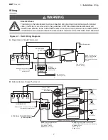
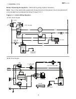
Connecting the thermostat with a voltage other than 24V may damage the heater. The RHT Series
requires a 24V connection to the thermostat. The RHT Series is equipped with an internal relay board. A
field supplied external transformer must be installed. See wiring diagram (Figures 2.1A-B).
Instructions for the following are detailed in the Tube Heater General Manual:
• Design considerations
• Hanger suspension and placement
• Tube layout and assembly
• Burner control box suspension
• Reflectors (and accessories)
• Venting and combustion air intake
• Gas requirements
• Baffle assembly
Note:
Electronic versions of all manuals are available at www.universalray.com
Gas Requirements
Type of Gas
Required Manifold
Pressure
Minimum Inlet
Pressure
Maximum Inlet
Pressure
Natural
3.5 Inches W.C.
5.0 Inches W.C.
14.0 Inches W.C.
Propane
10.0 Inches W.C.
11.0 Inches W.C.
14.0 Inches W.C.
IMPORTANT:
Consult the Tube Heater General Manual for gas connection requirements.


