12
RHT
Series
3.0
RHT Series Operation
• Sequence of Operation • Thermostat • Diagnostics
3.0
Operation
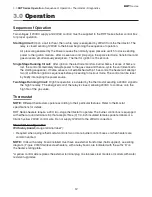
Sequence of Operation
Two voltages (120VAC supply and 24VAC control) must be supplied to the RHT Series burner control box
for proper operation.
Starting Circuit:
Upon a call for heat, the low fire relay is energized by 24VAC from the thermostat. The
relay is closed sending 120VAC to the blower beginning the sequence of operation.
Air pressure generated by the blower causes the normally open pressure switch to close, sending
power to the ignition module. After a seven-second pre-purge, the spark electrode, transformer and
gas valve are simultaneously energized. The trial for ignition is 15 seconds.
Single Stage Running Circuit:
After ignition, the electrode monitors burner flame. If sense of flame is
lost, the control immediately disrupts power to the gas valve and then re-cycle the unit (identical to
the starting sequence). If flame sense is not established within 15 seconds, the heater will attempt
two (2) additional ignition sequences before proceeding to lockout mode. The control can be reset
by briefly interrupting the power source.
Two Stage Running Circuit:
High fire operation is actuated by the thermostat sending a 24VAC signal to
the high fire relay. The energized coil of the relay is closed, allowing 24VAC to continue onto the
high fire of the gas valve.
Thermostat
NOTE:
Different thermostats operate according to their particular features. Refer to thermostat
specifications for details.
RHT Series heaters require a 24V, two-stage thermostat to operate. The burner control box is equipped
with either a round terminal strip that accepts three (3) 1/4-inch insulated female spade terminals or a
36-inch yellow 24VAC control wire. Do not supply 120VAC to the 24VAC connection.
Standard Configuration
With relay board
(orange terminal label*):
• Required when a single thermostat controls two or more burner control boxes or when heaters are
common vented.
NOTE:
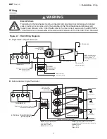
Units with a relay board installed must have an external transformer (field supplied), see wiring
diagram. (Figure 2.1B) Stainless steel heaters, with a relay board, are indicated with the suffix ‘D’ on
the heater’s rating plate.
*A yellow control wire replaces the external terminal plug on stainless steel models or models with water
resistant upgrades.


