background image

V350-35-TR34 Installation Guide

8

Unitronics 

Earthing the Power Supply 

To maximize system performance, avoid electromagnetic interference by: 

Mounting the controller on a metal panel. 
Earthing the controller’s power supply: connect one end of a 14 AWG wire to the chassis 
signal; connect the other end to the panel. 

Note: If possible, the wire used to earth the power supply should not exceed 10 cm in length.  
However, it is recommended to earth the controller in all cases. 


Communication Port 


Turn off power before making communications connections. 

Caution


Signals are related to the controller’s 0V; the same 0V is used by the power supply. 
Always use the appropriate port adapters. 
The serial port is not isolated. If the controller is used with a non-isolated external 
device, avoid potential voltage that exceeds ± 10V. 

Port 1 is type RJ-11 and may be set to either RS232 or RS485 via jumper as shown below.  
By factory default, the port is set to RS232, termination ON. 

Use RS232 to download programs from a PC, and to communicate with serial devices 
and applications, such as SCADA.   
Use RS485 to create a multi-drop network containing up to 32 devices. 
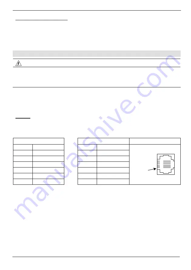
Pinouts

The pinouts below show the PLC port signals. 
To connect a PC to a port that is set to RS485, remove the RS485 connector, and connect the PC to 
the PLC via the programming cable. Note that this is possible only if flow control signals are not used 
(which is the standard case). 

RS232  

RS485** 

Controller 

Port 

Pin # 

Description 


Pin # 

Description 

1* DTR 

signal 


1  A 

signal 

(+) 

2

0V reference 


(RS232 signal) 

3

TXD signal 


(RS232 signal) 

4

RXD signal 


(RS232 signal) 

5

0V reference 


(RS232 signal) 

6* DSR 

signal 


6  B 

signal 

(-) 

Pin #1

*Standard programming cables do not provide connection points for pins 1 and 6. 
**When a port is adapted to RS485, Pin 1 (DTR) is used for signal A,  
  and Pin 6 (DSR) signal is used for signal B. 

Содержание Vision V350-35-TR34

Страница 1: ...ed analog weight and temperature measurement I Os via On board I O configuration Model dependent I O Expansion Modules Local or remote I Os may be added via expansion port or CANbus Information Mode This mode enables you to View Edit operand values COM port settings RTC and screen contrast brightness settings Calibrate the touchscreen Stop initialize and reset the PLC To enter Information Mode pre...

Страница 2: ...g this product the user must read and understand this document All examples and diagrams are intended to aid understanding and do not guarantee operation Unitronics accepts no responsibility for actual use of this product based on these examples Please dispose of this product according to local and national standards and regulations Only qualified service personnel should open this device or carry...

Страница 3: ...oller into the cut out ensuring that the rubber seal is in place 3 Push the 2 mounting brackets into their slots on the sides of the controller as shown in the figure to the right 4 Tighten the bracket screws against the panel Hold the bracket securely against the unit while tightening the screw 5 When properly mounted the controller is squarely situated in the panel cut out as shown in the figure...

Страница 4: ...5 kgf cm Do not use tin solder or any substance on stripped wire that might cause the wire strand to break Install at maximum distance from high voltage cables and power equipment Wiring Procedure Use crimp terminals for wiring use 26 12 AWG wire 0 13 mm 2 3 31 mm2 1 Strip the wire to a length of 7 0 5mm 0 250 0 300 inches 2 Unscrew the terminal to its widest position before inserting a wire 3 Ins...

Страница 5: ...part of a shaft encoder or as normal digital inputs If inputs 0 2 and 4 are set as high speed counters without reset inputs 1 3 and 5 can function as normal digital inputs Input Jumper Settings The tables below show how to set a specific jumper to change input functionality To access the I O jumpers you must open the controller according to the instructions beginning on page 9 Incompatible jumper ...

Страница 6: ...Guide 6 Unitronics npn sink Input Wiring Input wiring HSC input wiring pnp source Input Wiring Input wiring HSC input wiring Shaft encoder Analog Input Wiring Analog input wiring current 2 wire Analog input wiring current 3 wire ...

Страница 7: ...ect A clamping diode in parallel with each inductive DC load An RC snubber circuit in parallel with each inductive AC load Power Supply A non isolated power supply can be used if a 0V signal is connected to the chassis Install an external circuit breaker Guard against short circuiting in external wiring Double check all wiring before turning on the power supply Do not connect either the Neutral or...

Страница 8: ... 1 is type RJ 11 and may be set to either RS232 or RS485 via jumper as shown below By factory default the port is set to RS232 termination ON Use RS232 to download programs from a PC and to communicate with serial devices and applications such as SCADA Use RS485 to create a multi drop network containing up to 32 devices Pinouts The pinouts below show the PLC port signals To connect a PC to a port ...

Страница 9: ...tion jumpers must be moved To access the jumpers you must open the controller according to the instructions beginning on page 9 Opening the Controller Before performing these actions touch a grounded object to discharge any electrostatic charge Avoid touching the PCB board directly Hold the PCB board by its connectors 1 Turn off the power supply disconnect and dismount the controller 2 The back co...

Страница 10: ... applicable laws at any time at its sole discretion and without notice to discontinue or change the features designs materials and other specifications of its products and to either permanently or temporarily withdraw any of the forgoing from the market All information in this document is provided as is without warranty of any kind either expressed or implied including but not limited to any impli...

Отзывы: