background image


Unitronics 


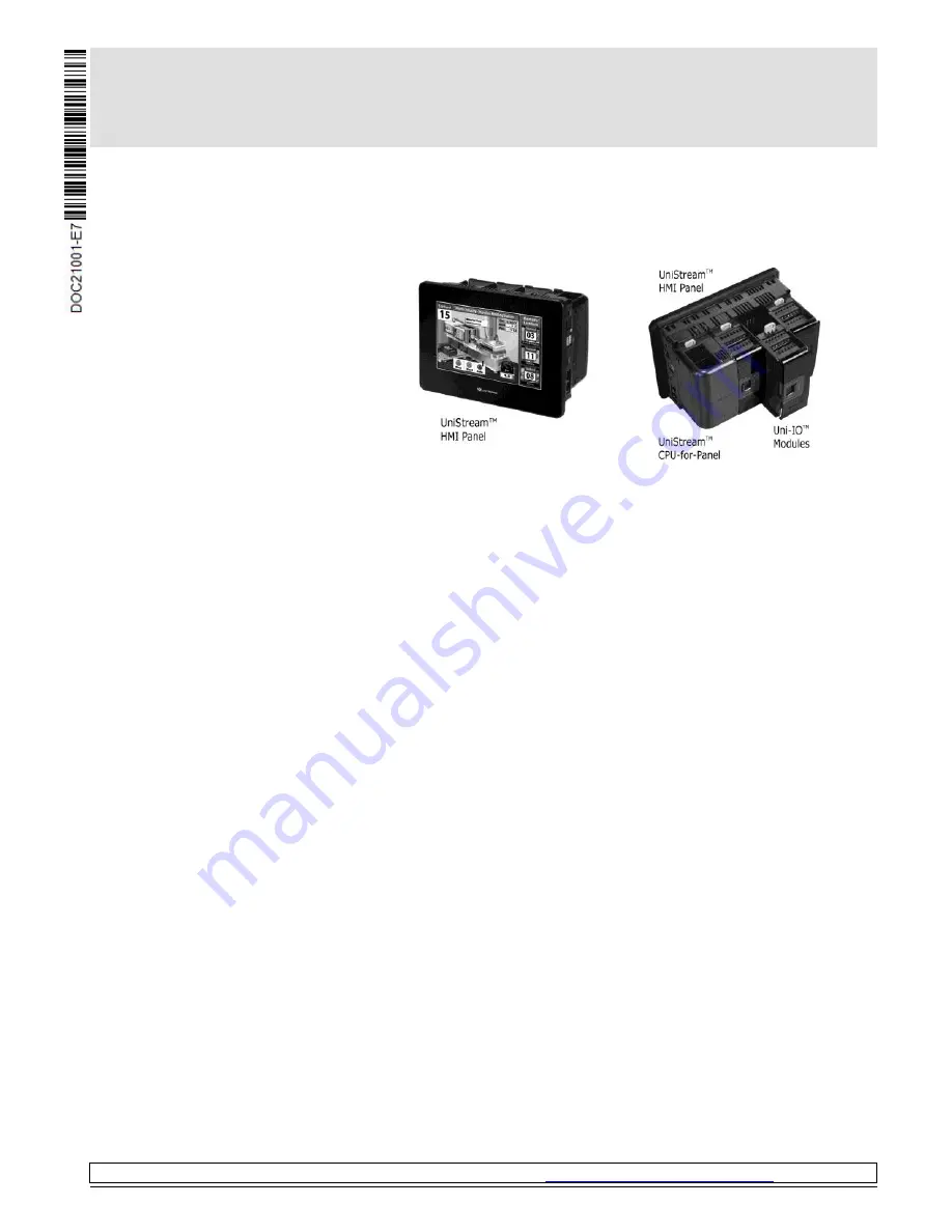
UniStream™ HMI Panel 

Installation Guide 
USP-070-B10, USP-070-B08 
USP-104-B10, USP-104-M10  
USP-156-B10 

Unitronics’ UniStream™ platform comprises control devices that provide robust, flexible 

solutions for industrial automation.  
This guide provides basic installation information for the UniStream™ HMI Panel.  
Technical specifications may be downloaded from the Unitronics website. 

The UniStream™ platform 

comprises CPU controllers, HMI 

panels, and local I/O modules  

that snap together to form an  

all-in-one Programmable Logic 
Controller (PLC).  
Expand the I/O configuration 

using a Local Expansion Kit or 

remotely via CANbus. 


CPU-for-Panel 

CPUs are Programmable Logic Controllers (PLCs), the heart of the 

UniStream™ platform. 
The CPU-for-Panel cannot operate independently. It must be plugged 

into the back of a UniStream™ HMI panel. The panel provides the CPU’s 

power source. The CPU-for-Panel comprises: 


IO/COM Bus connector for interfacing Uni-I/O™ & Uni-COM™ modules  


Isolated RS485 and CANbus ports 


Backup battery 

HMI Panels 

Available in 

different 

dimensions 

A high-resolution touch screen provides the operator interface for the 

system and the physical foundation for a PLC+HMI+I/Os all-in-one 

controller.  
The DIN-rail structure on the panel’s back is designed to physically 

support a CPU-for-Panel controller, Uni-I/O™ and/or Uni-COM™ 

modules. 
Each panel comprises: 


AUX connector to support the CPU 


1 audio-out 3.5mm jack 


1 microSD slot 


2 type A, USB host ports and 1 Mini-B USB device port 


2 Ethernet ports, RJ45, 10/100 Mbps 


1 power input connector, 12/24 VDC 

I/O Options 

Integrate I/Os into your system by using: 


On-board I/Os: snap onto the panel for an all-in-one configuration 


Local I/O via a Local Expansion Kit 


Remote I/O via EX-RC1 

Programming 

Software 

All-in-one UniLogic™ software, for hardware configuration, 

communications, and HMI/PLC applications, available as a free 

download from Unitronics web site. 


Use of this product is subject to a Unitronics Controller License Agreement, a copy of which can be found at  

http://unitronics.com/unistream/Agreements/UniLic1.pdf


Содержание UniStream USP-070-B10

Страница 1: ...acing Uni I O Uni COM modules Isolated RS485 and CANbus ports Backup battery HMI Panels Available in different dimensions A high resolution touch screen provides the operator interface for the system and the physical foundation for a PLC HMI I Os all in one controller The DIN rail structure on the panel s back is designed to physically support a CPU for Panel controller Uni I O and or Uni COM modu...

Страница 2: ...ct should be installed only by qualified personnel Failure to comply with appropriate safety guidelines can cause severe injury or property damage Do not attempt to use this device with parameters that exceed permissible levels Do not connect disconnect the device when power is on Environmental Considerations Ventilation 10mm 0 4 of space is required between the device top bottom edges and the enc...

Страница 3: ...liance 3 DIN rail structure Physical support for the CPU for Panel Uni I O and or Uni COM modules 4 12 24VDC power input Connection point for the HMI Panel s power source Connect the Terminal Block supplied with the kit to the end of the power cable 5 2 Ethernet RJ45 ports Support high speed Ethernet communications 6 USB Device Use for application download and direct PC UniStream communication 7 2...

Страница 4: ...nsiderations Allocate space for The HMI Panel including the CPU and any modules that will be installed on it Opening the doors of the CPU and modules For exact dimensions please refer to the Mechanical Dimensions shown below HMI Panel Mechanical Dimensions 7 Panel ...

Страница 5: ...UniStream Unitronics 5 10 4 Panel 15 6 Panel ...

Страница 6: ...ion 2 Slide the panel into the cut out ensuring that the Panel Mounting Seal is in place as shown on the right 3 Push the mounting brackets into their slots on the sides of the panel as shown below 4 Tighten the bracket screws against the panel Hold the brackets securely against the unit while tightening the screws When properly mounted the panel is squarely situated in the panel cut out as shown ...

Страница 7: ... from high voltage cables and power equipment Wiring Procedure Use crimp terminals for wiring use 26 12 AWG wire 0 13 mm2 3 31 mm2 1 Strip the wire to a length of 7 0 5mm 0 250 0 300 inches 2 Unscrew the terminal to its widest position before inserting a wire 3 Insert the wire completely into the terminal to ensure a proper connection 4 Tighten enough to keep the wire from pulling free Wiring Guid...

Страница 8: ...kets taking care to support the panel to prevent it from falling during this procedure The information in this documentreflects products at the date of printing Unitronics reserves the right subject to allapplicable laws at any time at itssole discretion and without notice to discontinue or change the features designs materialsand otherspecifications of its products and to either permanently or te...

Отзывы: