Unitronics IO-D16A3-RO16
4
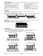
Increasing Contact Life Span
To increase the life span of the relay contacts and protect against potential damage by reverse EMF, connect one of the following:
A clamping diode in parallel with each inductive DC load.
An RC snubber circuit in parallel with each inductive AC load.
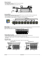
Addressing Inputs and Outputs on Expansion Modules
The PLC software assigns a unique address to each input and output in the system. The address comprises a letter and a
number. The letter indicates whether the I/O is an input (I) or output (O) and the number indicates its location (both the location of
the expansion module in the system and the I/O position on the module).
The I/O addressing scheme depends on the adapter type and location. Adapters may be local or remote. Local adapters must be
located close to the PLC. Remote adapters are connected to the PLC via CANbus. In addition, Unitronics offers I/O modules that
contain a built-in adapter. Available adapter options may be found at
1H
www.unitronics.com
.
The following example is based on a local EX-A1 adapter and may be used to calculate the number used by the PLC for inputs
and outputs:
32 + 16x + y
Where: X is the number representing the module location (0-7) and Y is the number of the input or output on the module (0-15).
The module is supplied with a set of labels – select the label appropriate to the position of the module. For more information, refer
to the
Configuring I/O Expansion Modules
topic in the on-line help of the software supplied with the controller.
The information in this document reflects products at the date of printing. Unitronics reserves the right, subject to all applicable laws, at any time, at its sole discretion, and without notice, to discontinue or change the features, designs,
materials and other specifications of its products, and to either permanently or temporarily withdraw any of the forgoing from the market. All information in this document is provided "as is" without warranty of any kind, either expressed or
implied, including but not limited to any implied warranties of merchantability, fitness for a particular purpose, or non-infringement. Unitronics assumes no responsibility for errors or omissions in the information presented in this document. In
no event shall Unitronics be liable for any special, incidental, indirect or consequential damages of any kind, or any damages whatsoever arising out of or in connection with the use or performance of this information. The tradenames,
trademarks, logos and service marks presented in this document, including their design, are the property of Unitronics (1989) (R"G) Ltd. or other third parties and you are not permitted to use them without the prior written consent of
Unitronics or such third party as may own them.
DIG-XL-D16R16 03-09


