Unitronics IO-D16A3-RO16
2
Wiring Considerations
Install an external circuit breaker. Guard against
short-circuiting in external wiring.
Do not connect unused pins. Ignoring this directive
may damage the device.
To avoid damaging wires, do not exceed a maximum
torque of 0.5 Nm (5 kgf·cm).
Use crimp terminals for wiring and use 26-12 AWG wire
(0.13mm
2
–3.31mm
2
).
Strip the wire to a length of 7±0.5mm (0.250–0.300”).
Do not route input cables together with output cables
through the same multi-core cable or wire.
Use wire that is correctly sized for the load. Allow for
voltage drop and noise interference with extended input
lines.
Note:
Connect the adapter 0V and the I/O 0V to the same line.
Do not use tin, solder, or any substance on stripped
wire that might cause the wire strand to break.
Daisy Chaining
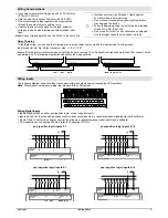
To facilitate wiring, you can wire the following pins in series (daisy chain). Use both pins provided for this purpose.
Input connector pin: n/p. Output connector pins: +V, 0V, C0, C1.
Ensure that the total current drain on any single line does not exceed 10A. If a specific pin requires more than 10A, connect it with
a separate wire. The following diagram demonstrates the wiring options:
Wiring Inputs
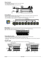
The following diagram shows the input connectors with pin numbers and corresponding LED numbers.
Note:
Where input numbers are stated, the intention is the LED number.
15 16 17 18 19 20 21 22 23 24 25 26 27 28
14
13
12
11
10
9
8
7
6
5
4
3
2
1
n/p RG
n/p
7
6
5
4
3
2
1
0
L ED #
AI1 AI0
AI2
14
13
12
11
10
9
8
15
L ED
#
Pin #
Pin #
RG
Wiring Digital Inputs
Inputs may be wired as either pnp (positive logic) or npn (negative logic).
Inputs 4 and 6 can function as high-speed counters, frequency measurers, or general purpose digital inputs (set in software).
Inputs 5 and 7 can function either as counter reset inputs or general purpose digital inputs (set in software).
For information on connecting RG pins, refer to
Connecting RG Pins
.
pnp (positive logic) inputs 0-7
pnp (positive logic) inputs 8-15
npn (negative logic) inputs 0-7
npn (negative logic) inputs 8-15
I8
I9
I1
0
I1
1
I1
2
I1
3
I1
4
I1
5
n/
p
RG


