CHAPTER 3: OPERATING INSTRUCTIONS
9100 SERIES REFLOW SOLDERING SYSTEM
990-606
3-3
4
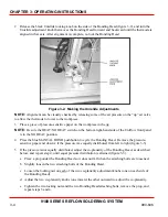
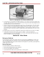
Align the jig on the rotating table using alignment pins, if present. Mount the jig with four socket
head cap screws. (See figure 3-1)
NOTE:
Set-ups are customized for each customer; alignment pins may not be present and you may not
use four screws for attaching your jig.
Figure 3-1. Installing a Typical Jig
NOTE:
There are three paired positions on the rotary table, marked JIG 1, JIG 2, and JIG 3. You may
mount up to three pairs at any one time and use any set pairs. Just be sure that the identical jigs (pairs)
are opposite each other in identically marked locations.
5
Repeat step 1 until the next location at which a jig will be installed is in front of you. Repeat step 2.
6
Continue as in steps 3 and 4 until all jigs are mounted.
Aligning the Bonding Head
The Bonding Head adjustments are found in the appropriate Bonding Head technical manual, cited in
table 1-1 of this manual.. Alignment of the Bonding Head for your specific bonding task is performed
as follows.
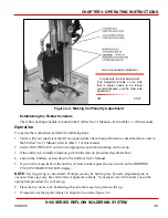
1 Place a sample piece to be bonded into the nest of one of the jigs, and move it into position under the
Bonding Head. As indicated above, this is done by simultaneously pressing the white TABLE
INDEX pushbutton and the left-hand green READY TO INDEX pushbutton.
Содержание 9100 Series
Страница 14: ......
Страница 25: ...9100 SERIES REFLOW SOLDERING SYSTEM 990 606 A 1 APPENDIX A SPECIFICATIONS...
Страница 32: ......

