CHAPTER 1: SYSTEM DESCRIPTION
9100 SERIES REFLOW SOLDERING SYSTEM
1-4
990-606
Controls and Indicators
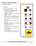
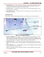
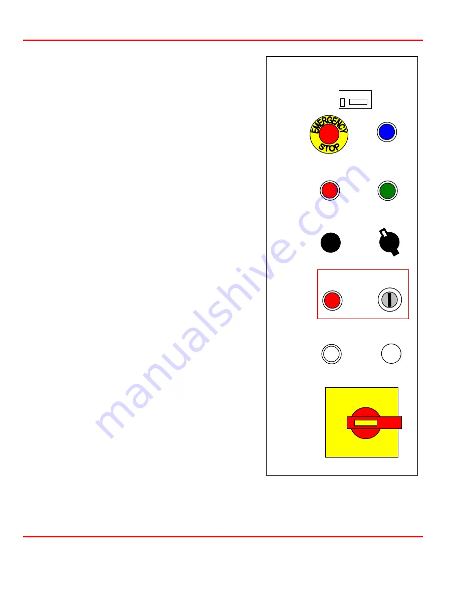
Control Panel
The control panel, shown in figure 1-2, contains the
following controls and indicators.
1
BONDING CYCLES COMPLETED
indicator -
(Grey LCD indicator with built-in reset button)
Indicates number of bonded parts.
2
EMERGENCY STOP
switch - (Red mushroom-head
pushbutton) Turns off power in an emergency. Not
intended for normal use.
3
RESET
switch/indicator - (Blue pushbutton with built-in
indicator) Used to reset guard switches on initial startup or
after an emergency stop. The blue indicator lights when
resetting is required; the light goes out after the RESET
switch is pressed.
4
CONTROL OFF
switch - (Red pushbutton) Used to
remove power to the control circuits and electrical sensors
and switches.
5
CONTROL
ON
switch/indicator - (Green pushbutton with
built-in indicator) Used to apply power to the control circuits
and electrical sensors and switches.
6
MONITOR/CAMERA
Not used.
7
JIGS IN PLACE
switch - (Four-position rotary switch)
Used to select either jig sets 1, 2, or 3, or all three jig sets.
8
GUARD OVERRIDE
indicator - (Red indicator) Lights
when override is in effect.
9
GUARD OVERRIDE
key switch - Allows operation of the
rotary table and jigs (for indexing) when the guard door is
open. Permits access to MANUAL BOND switch for set-up.
COUNTS
BONDING CYCLES
COMPLETED
RESET
CONTROL ON
CONTROL OFF
MONITOR/CAMERA
ON/OFF
JIGS
IN PLACE
1
2
3
ALL
GUARD OVERRIDE
TABLE
INDEX
MAINS ON
MAIN ISOLATOR
1
O
Figure 1-2. Control Panel
Содержание 9100 Series
Страница 14: ......
Страница 25: ...9100 SERIES REFLOW SOLDERING SYSTEM 990 606 A 1 APPENDIX A SPECIFICATIONS...
Страница 32: ......


