background image

4

USSC

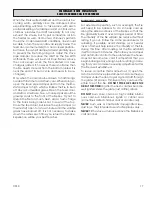
DAMPERS ON STOVE PIPES

When burning coal, we recommend a Barometric Draft 

Damper be installed at a safe convenient place between 

chimney and your furnace preferably less than 3’ from the 

flue collar.
When  you  have  installed  the  connector  pipe  between 

your  furnace  and  the  chimney,  tap  the  pipe  hard  with 

your fingernail. Remember the sound it makes - it will be a 

“ting” echoing inside the stove pipe. If later you tap and 

hear a muffled thud, you are building up soot in the pipe 

and should clean it. This pipe should be cleaned at least 

once or twice during the heating season.
DO NOT CONNECT TWO HEATERS TO THE SAME CHIMNEY 

FLUE. The National Fire Prevention Association recommends 

that wood burning appliances vent into a separate flue from 

gas or oil furnaces. If such an installation is contemplated, 

first check with a local building inspector to find out if a 

separate flue for a wood burner is required.
Use of a Barometric Draft Control 

(when burning wood)

 is 

recommended ONLY in the event your chimney creates 

excessive draft leading to an over-firing condition.

HEATED AIR DISCHARGE

The Clayton furnace is designed for use as a supplemental 

heating source. When used as a supplementary furnace, 

it is connected in conjunction with an oil, gas, or electric 

furnace  to  the  existing  duct  work  which  distributes  the 

heated air into several rooms and/or areas.

CONNECTING HOT AIR DUCT

TO FURNACE

We  strongly  recommend  that  the  hot  air  duct  work  be 

installed by a home heating specialist. If doing the instal

-

lation  yourself,  before  you  decide  which  installation  will 

best suit your needs, consult a qualified heating technician 

and follow his recommendations as to the safest and most 

efficient method of installation.
The following illustrations are the 

ONLY

 acceptable con

-

figurations when installed with existing oil or gas furnaces.

INSTALLATION EXAMPLES

INSTALLATION #1

With this installation, a back draft damper (optional) is in

-

serted into the heat run before the plenum of the existing 
furnace to prevent air from the existing furnace to blow 
back into the furnace when it is not in use.  When a back 
damper is employed, it should be located as close to the 
existing furnace plenum as practical.

IMPORTANT INFORMATION FOR ALL 

CONNECTOR PIPES

The  connector  pipe  must  be  constructed  and  installed 

so that it maintains clearances, keeps condensation and 

creosote within the pipe, and is capable of withstanding 

a 2100°F degree chimney fire.

1.   The connector pipe should slant down toward the fur

-

nace a minimum of 1/4” to the foot. At no time should 

the pipe turn downward toward the chimney or run 

horizontal.

2.   There should be no more than two 90 degree elbows.
3.   The  connector  pipe  should  never  be  longer  than  six 

feet. If it is absolutely necessary to make a run of more 

than  six  feet  (not  recommended)  use  extra  support 

brackets every 3 feet.

4.   The  connector  pipe  should  never  be  reduced  to  a 

smaller size than flue opening on the furnace.

5.   The connector pipe should not block the flue of the 

chimney or extend into it in any way.

6.   A good airtight thimble should be used to hold the con

-

nector pipe in the chimney. It should be constructed 

so the connector pipe can be removed for cleaning.

7.   The connector pipe should not leave the heated por

-

tion of the building to reach the chimney.

8.   The connector pipe should not pass from one story to 

the next before entering the chimney, nor should it pass 

through any closed or enclosed space.

9.   The  connector  pipe  and  any  elbows  must  be  of  24 

gauge or greater.

10. The connector pipe should not be located near or in 

a walk way or well traveled area.

11.  All male ends of connector pipe should run or point 

towards the furnace.

12. Install a cast iron adjustable damper in the first joint of 

the connector pipe, nearest to the flue collar.

Though United States Stove Company expressly Does Not


recommend the use of its furnaces to be installed  and/or 

used as a free-standing heater, it is possible to achieve a 

reasonably safe and functional installation IF certain stan

-

dard procedures are followed.  The following are guidelines 

only and are intended to enable the furnace user to obtain 

reasonable efficiency from his furnace, and with due re

-

spect to safety when installing as a “free-standing heater”.  

If installed correctly, and in accordance with the instructions 

found in this manual, your warm air furnace may be installed 

as a “space heater” within living quarters, cabins, garage, 

or workshop.  Please adhere to the following:
1.  The use of a cold air return and/or filter box is mandatory.  

This will not only increase your blower life and provide 

filtered air, it will also help prevent the blower or blowers 

from “capturing” heated air exiting from the top of the 

furnace heat outlets.

2.  If installed as purchased , without directing the heat 

away from the furnace itself, it will simply sit and cycle, 

turning the blowers off and on.  The thermostat may not 

function properly.

3.  All larger furnaces (or those with multi-speed blowers) 

absolutely require BACK PRESSURE

 to prevent premature 

motor winding failure.  If allowed to operate at high RPM 

(As in “FREE AIR” mode - no duct work or flow restrictions) 

the windings overheat, insulation melts and the motor 

simply burns up - not covered under warranty.

Содержание NITED STATES STOV 1602M

Страница 1: ...380 www usstove com SAFETY NOTICE If this furnace is not properly installed a house fire may result For your safety follow these installation instructions Contact local building or fire officials about restrictions and installation requirements in your area This furnace must be installed by a qualified technician Keep these instructions for future reference Installation Operator s Manual Safety Te...

Страница 2: ...setting the draft adjustment and the chimney to which the unit is attached The actual area that this unit will heat depends on factors such as the conditions of the building heat loss type of construction amount of insulation type of air movement the location of the unit and more importantly the duct work and return air facility Warning Do not alter this appliance in any way other than speci fied ...

Страница 3: ...ed slowly it produces tar and other organic vapors which combine with expelled moisture to form creosote The creosote vapors condense in the rela tively cool chimney flue of a slow burning fire As a result creosote residue accumulates on the flue lining When ignited this creosote makes an extremely hot fire The chimney connector and chimney should be inspected at least twice monthly during the hea...

Страница 4: ...um of 1 4 to the foot At no time should the pipe turn downward toward the chimney or run horizontal 2 There should be no more than two 90 degree elbows 3 The connector pipe should never be longer than six feet If it is absolutely necessary to make a run of more than six feet not recommended use extra support brackets every 3 feet 4 The connector pipe should never be reduced to a smaller size than ...

Страница 5: ...n order to insure proper furnace performance Failure to provide return air ducts of the specified size will void your warranty A filter should be installed in the cold air return Furnace fil ters should be checked and cleaned replaced regularly If return air is not provided the warm air distributed into your home will be restricted and the efficiency of the furnace is decreased Without a return ai...

Страница 6: ...nting brackets on the left side of the door frames as illustrated The slots in the brack ets and latches are for door seal adjustment Make the proper adjustments then tighten the nuts The door s gas ket should be snug against the door frame on the furnace Feed Door Illustration Ash Door Illustration 1 Feed Door Latch 1 Ash Door Latch 4 1 4 20 x 3 4 Hex Bolt 4 1 4 20 Kep Nut SHAKER GRATE HANDLE BRA...

Страница 7: ... the illustration Attach the shorter con duit assembly to the bottom of the box securing it with the nut on the fitting 5 Plug the wires onto the snap disc see wiring sche matic and then attach the box to the back of the unit using four of the 10 x 1 2 screws provided 6 Next mount the junction box and insulation using two of the 10 x 1 2 screws provided Install the 5 x 5 insu lation between the ca...

Страница 8: ...ICK REPLACEMENT If baffle replacement is necessary slide the baffle out until you can access the nuts thru the flue outlet Once the nuts have been removed slide the baffle off the rod and thru the opening in the firebrick You may have to remove one of the firebrick to make baffle removal easier There are 4 full brick and 1 half brick in the top of the fur nace Install the brick by inserting one en...

Страница 9: ...coal in on the shaker grates It should come up to about half of the first firebrick level Place crumpled paper over the coal and crisscross a couple handfuls of dry kindling wood 3 4 in thickness on top of paper Ignite the paper and close loading door Wait about 30 minutes until coal fire is established before adding more coal NOTE NEVER load coal over the level of firebrick Close by pass damper a...

Страница 10: ... a fire extinguisher into the firebox After chimney fire is over completely inspect system for damage before further use NEVERthrowwateronthefireoratthefurnace asrapidly expanding steam could result in a severe scalding Slow fires It is not recommended burning the Clayton furnace any more than necessary early in the fall and late spring as you cannot keep the firebox hot enough without overheating...

Страница 11: ...cap is not too close to the top of the chimney D Check chimney draft make sure chimney flue pipe is clean and chimney is of adequate height E Make sure you re not suffocating the fire with exces sive amounts of unburned wood F Slide baffle should be pulled out prior to load door opening 4 Problem Distribution blower vibrating Solution A Tighten blower wheel to motor shaft B Check for bad fan beari...

Страница 12: ...12 USSC PARTS DIAGRAM 11 12 13 16 15 17 14 7 10 5 2 3 6 30 29 4 3 2 1 35 3 8 9 24 26 25 27 17 16 3 19 18 20 28 34 21 22 32 33 23 31 ...

Страница 13: ...wide x 9 tall x 1 1 4 thick 891414 3 18 Slide Baffle 24231 1 19 Baffle Rod 86603 1 20 Lock Nut 1 2 13 83444 2 21 Gasket Flue Collar 88032 1 22 Flue Collar 40246 1 23 Flue Collar Ring 22761 1 24 Smoke Curtain 23800 1 25 Smoke Door Clip 23787 2 26 Carriage Bolt 1 4 20 x 1 1 4 Long 83445 2 27 Kep Nut 1 4 20 83250 2 28 Cabinet Side Left 69452 1 29 Cabinet Side Right 69453 1 30 Blank Receptacle Snap In...

Страница 14: ... for your home U S Stove offers the model UFB908 as an option and can be purchased from your local dealer The UFB908 utilizes a standard 16 x 20 filter that can be purchased from your local dealer or any hardware duct work supply store When installing a UFB908 follow the in stallation instructions supplied with the kit 6 7 8 USSC offers a forced induced draft blower kit as an option to upgrade you...

Страница 15: ...eal The installation is now ready to be plumbed to your exist ing hot water system Choose one of the three methods described in the Hot Water Coil instructions 6 Remove knockouts from the access panel and re attach to the furnace enclosure Have a qualified plumber connect your domestic hot water pipe to the coil with the appropriate fittings DR6 6 DRAFT REGULATOR OPTIONAL KIT In the unlikely event...

Страница 16: ... method with the highest portion of your fire bed in the center of the firebox The first flames will be long and generally orange or yellow and produce quite a bit of smoke As the gases burn off the flames become shorter change color and produce less smoke Once the fire is WELL ESTABLISHED add coal to the center of the firebox forming the cone Burning in this fashion allows heat to drive off the v...

Страница 17: ...ew minutes until the volatile gases have burned off It is not necessary to shake down the ashes each time you refuel the furnace Experience will be your best teacher BULLETIN RC454 A GUIDE TO BURNING COAL IN YOUR FURNACE BANKING THE FIRE For extended operation such as overnight the fire will need to be banked To do so heap coal up along the sides and back of the firebox so that the fire gradually ...

Страница 18: ...18 USSC NOTES ...

Страница 19: ...19 USSC NOTES ...

Страница 20: ... future reference When placing an order or for warranty claims please provide the following information found on the Certification Plate located below the ash door PART NUMBER PART DESCRIPTION MODEL NUMBER 1602M SERIAL NUMBER______________ United States Stove Company 227 Industrial Park Road P O Box 151 South Pittsburg TN 37380 423 837 2100 Customer Service 800 750 2723 Repair Parts 888 299 1440 ...

Отзывы: