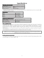
United States Stove Company King Pellet Stove KP130 Скачать руководство пользователя страница 10

-10-

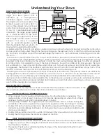
HOW YOUR STOVE WORKS

Your pellet stove utilizes a inclined 

auger fuel feed system that is 

operated by a microprocessor 

controlled digital circuit board. 

The digital circuit board allows the 

inclined auger fuel feed system to 

run in a timer-based, non-continuous 

cycle; this cycling allows the auger 

to run for a predetermined period 

of seconds. The auger pushes pellets 

up a chute located at the front/

bottom of the hopper which in turn 

falls through another chute into the 

burnpot. Your stove is equipped 

with an automatic ignition system 

that should ignite the fuel within 5-10 

minutes from pressing the ON button. 

As pellets enter the burn pot and ignite, outside air is drawn across the fuel and heated during the combustion 

process which is then pulled through the heat exchanger by the exhaust motor or draft fan. As the stove heats 

up, room air is circulated around the heat exchanger by means of a room air blower, distributing warm air into 

the room.

The amount of heat produced by the stove is proportional to the rate of the fuel that is burned, and this rate 

is controlled by the “HEAT RANGE” setting. In order to maintain combustion of the fuel at a desired rate, the air 

provided to the burn chamber by the exhaust or draft fan must be maintained precisely. Too little air will result 

in a flame that is non-energetic or lazy. If the fuel continues to flow with too little air for long enough, the burn 

pot will fill with too much fuel and the fire will smother out. To much air will result in a flame that is overactive 

or aggressive. The flame in this situation is typically very blue at the bottom and resembles a blow torch. If this 

situation continues, the fuel in the burn pot will be consumed and the fire will go out.

Matching the amount of air required for proper combustion to the fuel rate is the primary objective in effectively 

burning pellets of various brands and qualities in your stove. The air to fuel ratio can be adjusted to allow almost 

any fuel quality to burn effectively by following the procedures detailed in the remainder of this manual.

Because a forced draft pressure is required for the combustion process inside your stove, it is extremely important 

that the exhaust system be properly installed and maintained. And, that when operating your stove, you make 

sure that the viewing door is properly sealed.

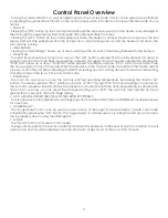
Understanding Your Stove

4 Digit Display

Up / Down

Buttons :

Heat Range

Room Fan

Draft Fan

Auto Mode

Indicator

Auger Delay

Indicator & Button

Off Indicator

& Button

On Indicator

& Button

1

1

2

2

3

3

4

4

A

A

B

B

TOLERANCES


EXCEPT


AS


NOTED

HOLES

 .005"

DECIMAL 

.XX = 0.03   XXX = 0.010

ANGULAR

 2 

DESCRIPTION

FINISH

REFERENCE

SCALE

DWN BY

DATE

SIZE

REV

TITLE

NUMBER

UNITED STATES STOVE COMPANY

ESTABLISHED 1869

KING PELLET STOVE

5502

A

B

5502

ASSEMBLY

WHO

2/8/2013


1  

OF

 1 

SHEET

© 2010 United States Stove Company

ALL RIGHTS RESERVED

THE DATA CONTAINED HEREIN IS PROPRIETARY TO U. S.

STOVE COMPANY.  THIS DATA SHALL NOT BE DUPLICATED,

TRANSFERRED, MADE AVAILABLE, OR USED BY ANY THIRD

PARTY FOR ANY PURPOSE EXCEPT SPECIFICALLY

AUTHORIZED IN WRITING BY U. S. STOVE COMPANY.

GENERAL NOTES:


ALL FORMED DIMENSIONS ARE TO

THE OUTSIDE OF THE PART,

UNLESS SPECIFIED OTHERWISE.

REVISION HISTORY

REV

DESCRIPTION

DATE

BY

A

INITIAL RELEASE

Date

Who?

Figure 10

Digital Control Panel

PANEL/REMOTE CONTROLS

The operation of this appliance can be controlled from the panel located on the side of the 

stove and/or by the remote control. The control functions are as follows:

A. 

ON/OFF SWITCH (“POWER” BUTTON)

• 

When pushed, the stove will automatically ignite. No other fire starter is necessary. The 

igniter will stay on for at least 10 and up to 12 minutes, depending on when Proof of Fire is 

reached. The fire should start in approximately 5 minutes.

• 

After pushing “POWER”, the auger motor is on for 3.5 minutes, off for 1 minute. During the 

remainder of the start-up period, the auger motor operates on the heat range “1” setting.

•  During start up the heat level advance (Up and Down keys) will change the heat range 

indicator level accordingly, but there is no change in the stoves operating conditions until 

start-up is completed.

•  During start-up ignition must occur within 12 minutes or the stove will error out and show E3.

•  During the start-up phase, the Mode key does not function.

B. 

HEAT RANGE ARROW BUTTONS

•  These buttons when pushed will set the pellet feed rate, hence the heat output or heat 

range of your stove. When using the hand-held remote this function can be performed with 

the “Up/Down” buttons.

•  The levels of heat output will incrementally change on the bar graph starting from heat 

range “1” to heat range “5”.

Содержание King Pellet Stove KP130

Страница 1: ...E FOR FUTURE REFERENCE United States Stove Company 227 Industrial Park Road South Pittsburg TN 37380 Please read this entire manual before installation and use of this appliance Failure to follow thes...

Страница 2: ...he closed container of ashes should be placed on a non combustible surface or on the ground well away from all combustible materials pending final disposal The exhaust system should be checked monthly...

Страница 3: ...nimum of 40 lbs per cubic ft 1 4 to 5 16 diameter length no greater than 1 5 not less than 8 200 BTU lb moisture under 8 by weight ash under 1 by weight and salt under 300 parts per million Pellets th...

Страница 4: ...an NFI certified specialist IMPROPER INSTALLATION The manufacturer will not be held responsible for damage caused by the malfunction of a stove due to improper venting or installation Call 800 750 272...

Страница 5: ...0 203mm CORNER D Adjacent wall to unit 8 00 203mm ALCOVE E Alcove depth 36 00 914mm 5500 M only F Alcove height 60 00 520mm CLEARANCES Your pellet stove has been tested and listed for installation in...

Страница 6: ...ove use a 3 inch to 4 inch adapter for 4 inch pipe Connection at back of stove must be sealed using Hi Temp RTV Use 4 inch vent if the vent height is over 12 feet or if the installation is over 2 500...

Страница 7: ...ot 2 13m clearance from any grade when adjacent to public walkways E Minimum 2 foot 0 61m clearance above any grass plants or other combustible materials F Minimum 3 foot 0 91m clearance from an force...

Страница 8: ...can be used if your heater is below ground level by simply adding the clean out section and vertical pipe inside until ground level is reached With this installation you have to be aware of the snowd...

Страница 9: ...to the heater Installation SPECIAL MOBILE HOME REQUIREMENTS WARNING Do not install in a sleeping room CAUTION The structural integrity of the mobile home floor wall and ceiling roof must be maintained...

Страница 10: ...e a forced draft pressure is required for the combustion process inside your stove it is extremely important that the exhaust system be properly installed and maintained And that when operating your s...

Страница 11: ...at will not properly control the unit When adjusting the Draft Fan setting try only 1 setting above or below the heat setting It is better to leave the stove in the automatic mode ROOM FAN The room fa...

Страница 12: ...2 conductor wire Put female plug fittings on the lead wires to your low voltage thermostat Plug one thermostat lead onto each of the terminal posts on the circuit board The stove will now drop back t...

Страница 13: ...w LEDs will be off 5 Hopper Switch Test The display will show hppr The ON LED is lit If the hopper switch is open lid is open the HEAT RANGE LED will turn on If the lid is closed the HEAT RANGE LED wi...

Страница 14: ...the heat exchanger in the stove reaches the factory preset temperature Attempts to achieve heat output rates that exceed heater design specifications can result in permanent damage to the heater First...

Страница 15: ...ck panel or opening the exhaust system for any inspection cleaning or maintenance work Never perform any inspections cleaning or maintenance on a hot stove Do not operate stove with broken glass leaka...

Страница 16: ...We recommend using a high quality glass cleaner Should a build up of creosote or carbon accumulate you may wish to use 000 steel wool and water to clean the glass DO NOT use abrasive cleaners DO NOT p...

Страница 17: ...re that the viewing door is closed and sealed properly If not adjust door catch and or replace door gaskets Check that all outside connections are clear of any obstructions Check the exhaust system cl...

Страница 18: ...tor This indicates that the stove is in normal operation and is running in the automatic mode However either the draft fan or room fan setting is manually configured Flashing Draft Fan Setting Indicat...

Страница 19: ...19 GRAY BLACK Wiring Diagram CORRECT WRONG Insure the wires are connected to the bottom two prongs of the hopper switch as shown...

Страница 20: ...40 Lock Nut 2 16 25480MB Access Panel 1 17 80461 Power Supply Cord 1 18 80462 Receptacle 3 Prong 1 19 891164 Auger Housing Weldment 1 20 891141 Auger 1 21 891189 Top Bushing Plate 1 22 891132 Bushing...

Страница 21: ...21 11 3 2 1 5 6 4 7 9 8 10 12 Parts Diagram 47 46 48 49 50...

Страница 22: ...07 Date _____________________ Engineer Name ________________________________ License No ____________________________________ Company _____________________________________ Telephone No _______________...

Страница 23: ...terruptions or uctuations of electrical power supply to the appliance Non USSC venting components hearth components or other accessories used in conjunction with the appliance USSC s obligation under...

Страница 24: ...s pi ces d tach es Gardez ce manuel dans un lieu s r pour toute consultation ult rieure Lorsque vous nous crivez donnez toujours le num ro de mod le complet qui se trouve sur la plaque signal tique fi...

Страница 25: ...t autoris es et approuv es par crit par USSC et ou 9 les interruptions ou uctuations de l alimentation lectrique de l appareil Composants d vacuation des gaz composants de l tre ou accessoires utilis...

Страница 26: ...____________________________ Service de 07 Date _____________________ Nom de l ing nieur ____________________________ N de licence _________________________________ Compagnie _________________________...

Страница 27: ...2 15 83542 4 40 crou 2 16 25480MB Panneau D acc s 1 17 80461 Cordon D alimentation 1 18 80462 R ceptacle 3 Prong 1 19 891164 Auger Logement Weldment 1 20 891141 Vrille 1 21 891189 Top Bushing Plate 1...

Страница 28: ...21 Sch ma des pi ces 11 3 2 1 5 6 4 7 9 8 10 12 47 46 48 49 50...

Страница 29: ...SOSTAT MARRON MARRON NOIR BLANC ROUGE BLEU ORANGE PRISE MOLEX AU CIRCUIT IMPRIM PCB PRINCIPAL NOIR NOIR NOIR BLANC BLANC SOUFFLANTE DE DISTRIBUTION VENTILATEUR D VACUATION THERMISTOR Sch ma de c blage...

Страница 30: ...eux fois par seconde Cela indique que le po le fonctionne normalement et qu une condition de temp rature excessive existe provoquant l arr t du combustible Indicateur de r glage du niveau de chaleur H...

Страница 31: ...e V rifiez que le raccordement du pressostat au foyer ne contienne aucune cendre ni obstruction Le syst me vis sans fin est bloqu ou il y a une vo te de combustible dans la tr mie qui emp che le combu...

Страница 32: ...le et d paisseur correctes doivent tre utilis es NE substituez PAS le verre avec des mat riaux alternatifs Contactez votre revendeur autoris pour obtenir ce verre R installez le nouveau verre en le fi...

Страница 33: ...fi peut effectuer ces travaux Il est aussi recommand qu avant chaque saison de chauffage le syst me complet soit inspect nettoy et si n cessaire r par par un professionnel Pour nettoyer la chemin e d...

Страница 34: ...sur le bouton OFF arr t et ensuite de nouveau sur le bouton ON marche pour commencer une nouvelle s quence de mise en route 2 Si le po le a refroidi il se r initialisera l tat OFF arr t ce moment l vo...

Страница 35: ...de l eau sal e 11 Bois non s ch ou 12 Produits du papier carton contreplaqu ou panneau de particules L interdiction de br lage de ces mat riaux n interdit pas l utilisation d allume feu compos s de pa...

Страница 36: ...fin se met en marche plein r gime Si le fusible de la vis sans fin n a pas saut et que le circuit de d tection fusible fonctionne le voyant DEL Heat Range du degr de chaleur sera allum et les trois au...

Страница 37: ...justez le r glage du ventilateur de tirage essayez seulement 1 r glage au dessus ou en dessous du r glage de chaleur Il est pr f rable de laisser le po le en mode automatique VENTILATEUR DE LA PI CE L...

Страница 38: ...rage forc e est n cessaire au processus de combustion l int rieur de votre po le il est extr mement important que le syst me d vacuation soit install correctement et maintenu Et que lors du fonctionne...

Страница 39: ...r Frais Figure 8 Emplacements D vacuation Arriv e EXIGENCES SP CIALES POUR MAISON MOBILE INSTALLATION AUX U UNIQUEMENT AVERTISSEMENT Ne pas installer dans une chambre coucher ATTENTION L int grit stru...

Страница 40: ...onducteurs Placez les raccords m les sur les fils de connexion votre thermostat basse tension Branchez un fil de thermostat sur chacun des bornes de la carte de circuit imprim Le po le va maintenant r...

Страница 41: ...u regard et le tuyau vertical l int rieur jusqu ce que le niveau du sol soit atteint Avec cette installation vous devez faire attention la ligne d amas de neige la pelouse et les feuilles mortes Nous...

Страница 42: ...C D gagement minimum de 3 pieds 0 91m partir de toute construction adjacente D D gagement minimum de 7 pieds 2 13m de tout passage lorsqu il est adjacent des all es publiques E D gagement minimum de 2...

Страница 43: ...nnect au raccord de conduite fourni au dos du po le utilisez un adaptateur de 3 4 pouces pour le tuyau de 4 pouces Le raccordement l arri re du po le doit tre scell en utilisant un produit vulcanis RT...

Страница 44: ...re minimum plus grand afin d obtenir un acc s commode au panneau de contr le FIGURE 3 D GAGEMENTS DE LA PAROI LAT RALE INSTALLATION EN PARALL LE FIGURE 4 D GAGEMENTS DE LA PAROI LAT RALE INSTALLATION...

Страница 45: ...cialiste certifi NFI NE CONNECTEZ PAS CETTE UNIT UN CONDUIT OU CIRCUIT DE DISTRIBUTION D AIR INSTALLATION INCORRECTE Le fabricant ne sera pas tenu responsable des dommages caus s par un dysfonctionnem...

Страница 46: ...ation of Pellet Fuel Industries Minimum de 40 lbs par pied cube diam tre de 1 4 5 16 longueur non sup rieure 1 5 pas moins de 8 200 BTU lb humidit inf rieure 8 en poids cendres moins de 1 en poids et...

Страница 47: ...d entretien ou de nettoyage Les cendres doivent tre jet es dans un conteneur m tallique avec un couvercle d ajustement serr Le conteneur ferm dans lequel se trouvent les cendres devra tre plac sur une...

Страница 48: ...des officiels dans vos services locaux de la construction ou des incendies afin de conna tre les restrictions et les exigences d inspection et d terminer si vous avez besoin d un permis de construire...

Отзывы: