F
INSTALLATION
(%,D'$7(D'8
The longer the run of pipe in your installation (both with inserts
and freestandings), the more restriction there is in the system.
Therefore, larger diameter pipe should be used.
,\ &' Z
vent length.
/ G K&( %`5
A <
feet.
%`5 Q
*( [\
'Z
,'
?Z
/ G - &Z
`-
( 'Z
NOTE: At altitudes above 3,000 feet, we suggest the use of
,\%`5 F
>/-G-.''1./-9 /''
> 0*@
-.(
0 5+`
& 0
1 & 2.
2. Locate position of hole in wall; directly behind stove
exhaust> '@
3. Always maintain 3” clearance from combustible materials.
4. A 5+` 5+`
instructions.
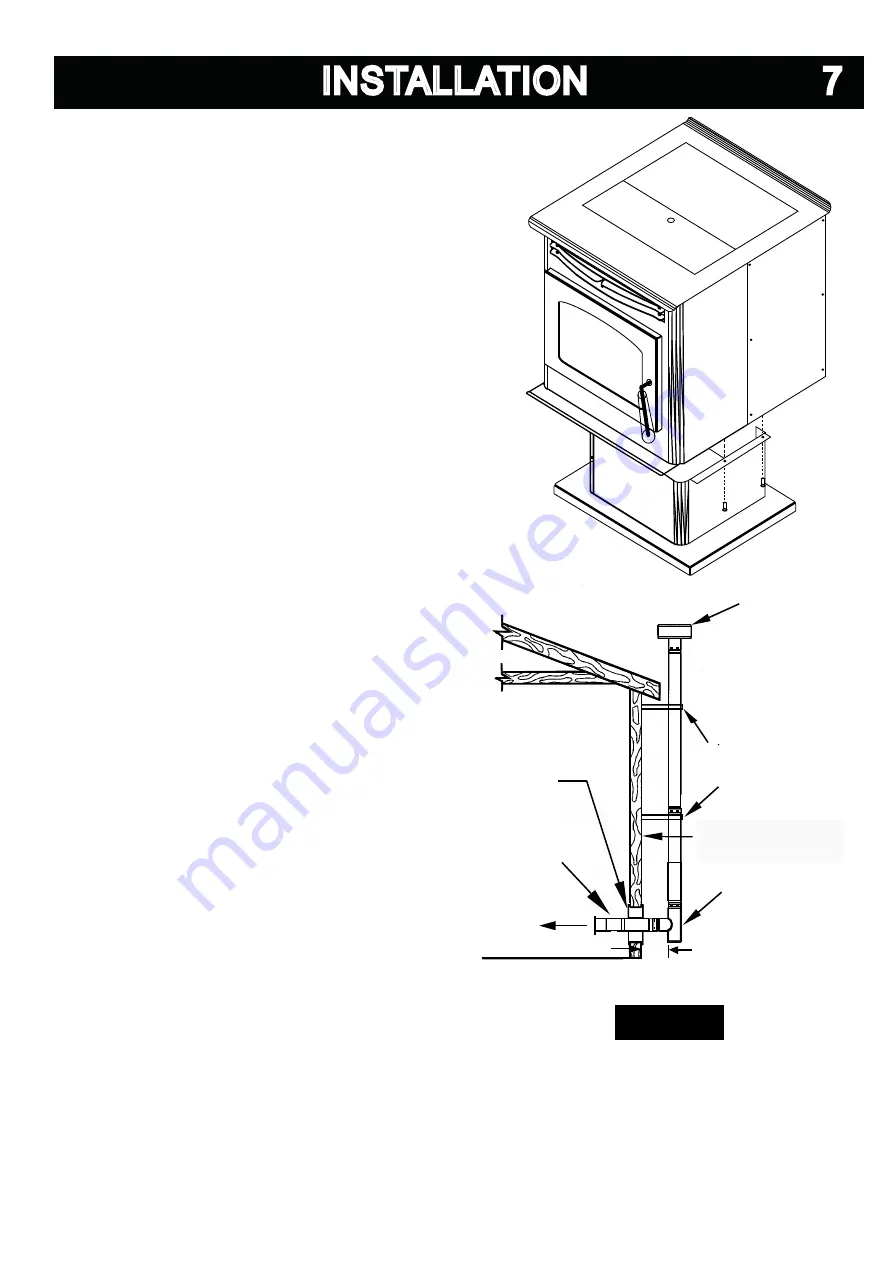
5. Attach enough piping to penetrate and extend at least 6”
beyond exterior walls. An 8-foot vertical pipe run is sug-
gested where possible to reduce the possibility of smoke
spillage in the event of a loss of negative pressure.
6. Attach cap and seal outside wall thimbles with non-
hardening waterproof mastic.
F ermination should not be located so that hot exhaust
G
to children. Exhaust gases can reach temperatures of
'((0
Locate terminations: a) not less than 3 feet above any forced
air inlet located within 10 feet; b) not less than 4 feet below
G
gravity air inlet into any building; c) not less than two feet from
! F
! $ -
stallations must use a spark arrester.
FIGURE
FIGURE
VERTICAL ROOF VENT
WALL
THIMBLE
6” MINIMUM CLEARANCE
TO ANY COMBUSTIBLE
SURFACE
CLEAN-OUT TEE
A 90 DEGREE ELBOW
MAY ALSO BE USED
WALL STRAP
SEE VENT MANUFACTURER
FOR NUMBER AND SPACING
TO
APPLIANCE
L-VENT
ADAPTER
6” MINIMUM CLEARANCE
All manuals and user guides at all-guides.com


