


WirelessHART Toxic & Combustible Gas Detector
IM_TCD60-01
www.ueonline.com/vanguard
20
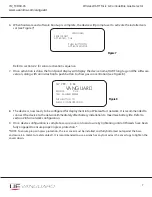
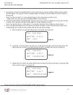
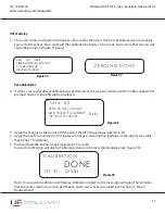
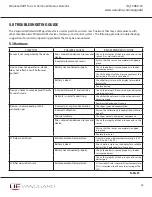
D. Connected: The device should now be joined to the network (see Figure 34). If the device fails
to join the wireless mesh network, consult the Troubleshooting Guide (see Section 5.0).
Note:
Data transfer is not possible yet.
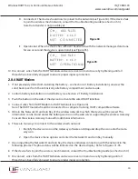
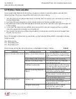
E. Operational: When the device has sufficient bandwidth with the network manager, data trans-
fer can occur and the device is operational (see Figure 35).
10. Disconnect wires from the HART terminals and secure cover onto enclosure by tightening until all
threads have been fully engaged to ensure proper ingress protection.
2.8.4 HART Modem
1. If not previously done (from installing the battery – see Section 2.1 Battery Installation), unscrew the
solid, back cover from the intrinsically safe battery compartment and set aside.
2. Confirm battery installation or install battery (see Section 2.1 Battery Installation).
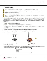
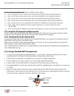
3. Push the button on the side of the device to activate the wired HART interface.
4. Connect wires from HART Modem to HART terminals (see Figure 24).
Note:
The HART modem should be connected to a computer running HART compatible software.
5. Obtain the Network ID and Join Key of the wireless network to which the device will be joined. This
information can be found under the Settings section on the web server supporting the wireless Gateway.
Consult the wireless Gateway manual for additional information.
6. There are two ways to connect to the wireless mesh network.
1. Identify the device icon on the Gateway software and drag and drop the icon onto the Gate-
way icon.
2. Open the device menu options and enter the Network ID and Join Key manually.
7. Upon inputting the Network ID and Join Key, the device initializes connection with the network in the
following phases. The phase status will be indicated on the device display. Refer to Figures 31-35.
8. If the device fails to join the wireless mesh network, consult the Troubleshooting Guide (see Section 5.0).
9. Disconnect wires from the HART terminals and secure cover onto enclosure by tightening until all
threads have been fully engaged to ensure proper ingress protection.
B AT T E R Y: X . X X V
N E T: C O N N E C T E D
Figure 34
C H
4
: X X X % L E L
Figure 35
B AT T E R Y: X . X X V
N E T: O P E R AT I O N
A L
C H
4
: X X X % L E L


