


035-20464-002 Rev. A (1004)
8
Unitary Products Group
SECTION IV: GAS PIPING
GAS SAFETY
IMPORTANT:
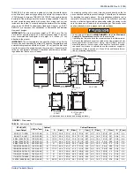
Plan your gas supply before determining the correct gas
pipe entry. Use 90-degree service elbow(s), or short nipples and con-
ventional 90-degree elbow(s) to enter through the cabinet access holes.
GAS PIPING INSTALLATION
Properly sized wrought iron, approved flexible or steel pipe must be
used when making gas connections to the unit. If local codes allow the
use of a flexible gas appliance connection, always use a new listed con-
nector. Do not use a connector that has previously serviced another gas
appliance.
Some utility companies or local codes require pipe sizes larger than the
minimum sizes listed in these instructions and in the codes. The furnace
rating plate and the instructions in this section specify the type of gas
approved for this furnace - only use those approved gases. The instal-
lation of a drip leg and ground union is required. Refer to Figure 9.
IMPORTANT:
An accessible manual shutoff valve must be installed
upstream of the furnace gas controls and within 6 feet (1.8 m) of the fur-
nace.
The furnace must be isolated from the gas supply piping system by
closing its individual external manual shutoff valve during any pressure
testing of the gas supply piping system at pressures equal to or less
than 1/2 psig (3.5 kPa).
Gas piping may be connected from either side of the furnace using any
of the gas pipe entry knockouts on both sides of the furnace. Refer to
Figure 1 dimensions.
GAS ORIFICE CONVERSION FOR PROPANE (LP)
This furnace is constructed at the factory for natural gas-fired operation,
but may be converted to operate on propane (LP) gas by using a fac-
tory-supplied LP conversion kit. Follow the instructions supplied with
the LP kit. Refer to Table 7 or the instructions in the propane (LP) con-
version kit for the proper gas orifice size.
An overpressure protection device, such as a pressure regulator,
must be installed in the gas piping system upstream of the furnace
and must act to limit the downstream pressure to the gas valve so it
does not exceed 0.5 PSI (14" w.c. (3.48 kPa). Pressures exceeding
0.5 PSI (14” w.c. (3.48 kPa) at the gas valve will cause damage to
the gas valve, resulting in a fire or explosion or cause damage to
the furnace or some of its components that will result in property
damage and loss of life.
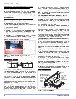
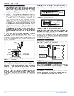
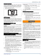
FIGURE 6:
Gas Valve
INLET
WRENCH
BOSS
INLET
PRESSURE
PORT
ON
OFF
ON/OFF SWITCH
(Shown in ON position)
MAIN REGULATOR
ADJUSTMENT
OUTLET
OUTLET
PRESSURE
PORT
VENT PORT
CHECKING THE GAS PRESSURES
1.
The pressure ports on the gas valve are marked OUT P and IN
P.
2.
The manifold pressure must be taken at the port marked OUT P.
3.
The inlet gas supply pressure must be taken at the port marked
IN P.
4.
Using a 3/32” (0.2 cm) Allen wrench, loosen the set screw by
turning it 1 turn counter clockwise. DO NOT REMOVE THE
SET SCREW FROM THE PRESSURE PORT.
5.
Push one end the 3/8” (0.9 cm) ID flexible tubing over the pres-
sure port so that the body of the port is inside the tubing.
6.
Use a reducer connector to connect the 3/8” (0.9 cm) ID flexible
tube to a 1/4” (0.6 cm) ID flexible tube that is connected to a "U”
tube manometer or digital pressure measuring equipment.
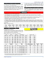
IMPORTANT:
The inlet gas pressure operating range table specifies
what the minimum and maximum gas line pressures must be for the
furnace to operate safely. The gas line pressure
MUST BE
a mini-
mum of:
•
7” W.C. (1.74 kPA) for Natural Gas
•
11” W.C. (2.74 kPA) for Propane (LP) Gas
in order to obtain the BTU input specified on the rating plate and/or
the nominal manifold pressure specified in these instructions and on
the rating plate.
TABLE 6:
Inlet Gas Pressure Range
INLET GAS PRESSURE RANGE
Natural Gas
Propane (LP)
Minimum
4.5” W.C. (1.12 kPa)
8.0” W.C. (1.99 kPa)
Maximum
10.5” W.C. (2.61 kPa)
13.0” (3.24 kPa) W.C.
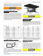
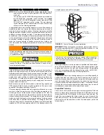
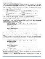
FIGURE 7:
Upflow Gas Piping
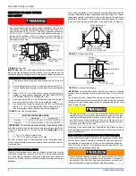
FIGURE 8:
Horizontal Gas Piping
The gas valve body is a very thin casting that cannot take any
external pressure. Never apply a pipe wrench to the body of the gas
valve when installing piping. A wrench must be placed on the octa-
gon hub located on the gas inlet side of the valve. Placing a wrench
to the body of the gas valve will damage the valve causing improper
operation and/or the valve to leak.
LoNOx furnaces requiring propane (LP) gas must have the LoNOx
screens removed prior to installation and operation. See propane
instructions 035-14445-000 or the start up procedure at the back of
these instructions on proper removal of the NOx screens.
EXTERNAL MANUAL
SHUTOFF VALVE
TO GAS
SUPPLY
TO GAS
SUPPLY
GROUNDED JOINT UNION
MAY BE INSTALLED
INSIDE OR OUTSIDE UNIT.
DRIP
LEG
MANUAL
SHUT-OFF
VALVE
DRIP
LEG
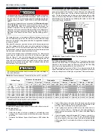
GAS
PIPE
GAS BURNERS
GAS VALVE
GAS
PIPE
DRIP
LEG
MANUAL
SHUT-OFF VALVE


