


035-20464-002 Rev. A (1004)
Unitary Products Group
11
SECTION VI: TWINNING AND STAGING
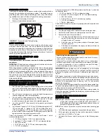
NOTE:
There are two different integrated control modules that can be
used on these models. They are part # 031-01933-000 and 031-
01267-001.
You can twin two 031-01933-000 integrated control modules or
two 031-01267-001 integrated control modules. You
cannot
twin
one 031-01933-000 integrated control module and one
031-01267-001 integrated control module. The two integrated
control modules do not communicate with each other so they
will not work in a twinning application.
In applications where more heating capacity or more airflow capacity is
needed than what one furnace can deliver, twinning can be used to
make two furnaces operate in tandem. When two furnaces are installed
using the same duct system, it is very important that the two furnace cir-
culating air blowers operate in unison. If one blower starts before the
second blower, the duct system will become pressurized and the blower
on the second furnace will turn backwards causing the second furnace
to overheat, resulting in damage to the furnace. Twinning is used to
make two furnaces operate in tandem, using one duct system, one
room thermostat and causing both furnaces to turn on and off simulta-
neously.
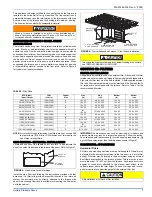
TWINNING DUCT SYSTEM
Twinned furnaces must only be applied on a common duct system. A
single air supply plenum must be used for both furnaces and coil(s).
Separate plenums and supply ducts systems cannot be utilized. A sin-
gle return air plenum, common to both furnaces must be used. It is sug-
gested that a return platform be utilized, with bottom air entrance into
each furnace. If a side entrance return system is used, the common
return duct must be divided equally so as to supply each furnace with
an equal amount of return air.
Both furnaces must be identical models in both heating capacity and
CFM capacity. Both furnaces must be operated on the same motor
speed tap. See typical application, Figure 14.
If furnace staging is desired with two single stage furnaces on a com-
mon duct, where the gas burner on the first furnace operates on W1
and the gas burner on the second furnace operates on W2, then the
use of an air-mixing device in the plenum to mix the air from both fur-
naces is strongly recommended. The mixing device must be installed
before any ducts that supply air to occupied spaces. Twinning causes
both indoor fans to operate simultaneously. If a mixing device is not
used, any ducts that are connected down stream from the furnace that
operates on W2, will be supplying cold air in the Heating mode to the
occupied spaces unless W2 is energized.
IMPORTANT:
When two furnaces are twinned, typical system total air-
flow will be approximately 85% of additive individual furnaces, i.e., two
2000 CFM units will yield a total 3400 CFM.
GAS PIPING
Furnace gas supplies must be provided as specified with these instruc-
tions. Since the furnaces are side by side, with no space between, gas
supplies must enter on the right and left respectively. All gas piping
must be in accordance with the national fuel gas code, ANSI Z223.1,
latest edition, and/or all local code or utility requirements.
TWINNING
In applications where more heating capacity or more airflow capacity is
needed than what one furnace can deliver, twinning can be used to
make two furnaces operate in tandem, using one duct system and one
room thermostat. When one duct system is used for two furnaces, it is
necessary that the two blowers operate in unison. The twinning function
of the board in this furnace ensures that both blowers turn on and off
simultaneously, and operate on the same blower speed.
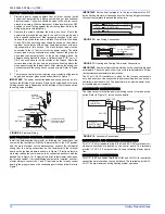
Single-Wire Twinning
The control in the furnace has the single-wire twinning feature. With this
feature, a single wire is connected between the TWIN terminal on one
furnace board to the TWIN terminal on the second furnace board. The
board then communicates the blower status from one furnace to the
other along this wire. This communication makes the second furnace
blower come on at the same time, and on the same speed, as the first
furnace blower.
Before installing the relay and wiring, disconnect electrical power to
both furnaces. Failure to cut power could result in electrical shock
or equipment damage.
The relay must not be installed in any location where it could be
exposed to water. If the relay has been exposed to water in any
way, it must not be used.
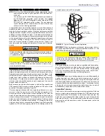
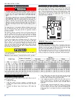
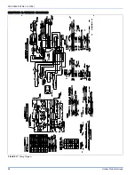
FIGURE 13:
Typical Twinned Furnace Application
If a return duct is connected to only one furnace (with a connection
between the two furnaces) an imbalance in the airflow will occur
and the furnace furthest from the return plenum will overheat.
VENT PIPE
ELECTRICAL
SUPPLY
GAS SUPPLY
(both sides)
1 COIL FOR
EACH FURNACE
COMMON
SUPPL
Y
PLENUM
SUPPLY
AIR


