


035-20464-002 Rev. A (1004)
Unitary Products Group
7
This appliance is design certified for line contact when the furnace is
installed in the horizontal left or right position. The line contact is only
permissible between lines that are formed by the intersection of the top
and two sides of the furnace and the building joists, studs or framing.
This line may be in contact with combustible material.
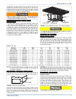
SUSPENDED FURNACE / CRAWL SPACE
INSTALLATION
The furnace can be hung from floor joists or installed on suitable blocks
or pad. Blocks or pad installations shall provide adequate height to
ensure the unit will not be subject to water damage. Units may also be
suspended from rafters or floor joists using rods, pipe angle supports or
straps. Angle supports should be placed at the supply air end and near
the blower deck. Do not support at return air end of unit. All four sus-
pension points must be level to ensure quite furnace operation. When
suspending the furnace use a secure platform constructed of plywood
or other building material secured to the floor joists. Refer to Figure 4
for typical crawl space installation.
SECTION III: FILTERS
FILTER INSTALLATION
All applications require the use of an external filter. Filter(s) and the filter
retainer are not provided on all models Some models are shipped with a
high velocity filter that must be field installed. A field-supplied external
filter and filter retainer hardware must be provided if the filter and the fil-
ter retainer are not shipped with the furnace. Refer to Table 4 for the
recommended filter size.
NOTE:
Air velocity through throwaway type filters may not exceed 300
feet per minute (91.4 m/min). All velocities over this require the
use of high velocity filters.
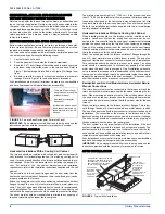
SIDE RETURN - EXTERNAL INSTALLATION
Locate and knock out the square corner locators. These indicate the
size of the cutout to be made in the furnace side panel. Refer to Figure 7.
Install the side filter rack following the instructions provided with that
accessory. If a filter(s) is provided at another location in the return air
system, the ductwork may be directly attached to the furnace side
panel. An accessory filter rack is available for mounting the filter exter-
nal to the cabinet.
IMPORTANT:
Some accessories such as electronic air cleaners and
pleated media may require a larger side opening. Follow the instruc-
tions supplied with that accessory for side opening requirements. Do
not cut the opening larger than the dimensions shown in Figure 1.
HORIZONTAL APPLICATION
Horizontal Filters
All filters and mounting provision must be field supplied. Filters(s) may
be located in the duct system external to the furnace or in a return filter
grille(s). Filters(s) may be located in the duct system using an external
duct filter box attached to the furnace plenum. Filters must be a mini-
mum distance of 18” (45.7 cm) from the furnace. Any branch duct (rect-
angular or round duct) attached to the plenum must attach to the
vertical plenum above the filter height. The use of straps and / or sup-
ports is required to support the weight of the external filter box.
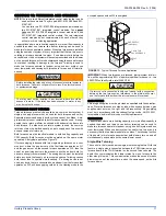
When a furnace is installed in an attic or other insulated space,
keep all insulating materials at least 12 inches (30.5 cm) away from
furnace and burner combustion air openings.
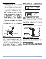
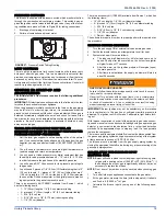
FIGURE 4:
Typical Suspended Furnace / Crawl Space Installation
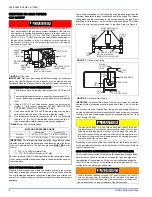
In any application where temperatures below freezing are possible,
see “BELOW FREEZING LOCATIONS”.
1” MAX. BETWEEN
ROD & FURNACE
SUPPORT
ROD
6” MIN BETWEEN
ROD & FURNACE
1” MAX. BETWEEN
ROD & FURNACE
ANGLE IRON
BRACKET
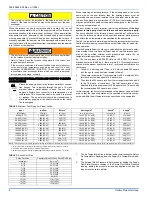
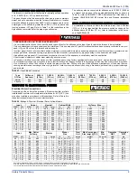
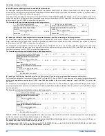
TABLE 5:
Filter Sizes
BTU/H (kW)
Input / Output
CFM
(m³/min)
Cabinet
Size
Side
(in)
Side
(cm)
Bottom
(in)
Bottom
(cm)
40/32 (11.71/9.38)
1200 (33.98)
A
16 x 25
40.6 x 63.5
14 x 25
35.6 x 63.5
60/48 (17.57/14.07)
1200 (33.98)
A
16 x 25
40.6 x 63.5
14 x 25
35.6 x 63.5
80/64 (23.42/18.76)
1200 (33.98)
A
16 x 25
40.6 x 63.5
14 x 25
35.6 x 63.5
80/64 (23.42/18.76)
1600 (45.31)
B
16 x 25
40.6 x 63.5
16 x 25
40.6 x 63.5
80/64 (23.42/18.76)
2200 (62.30)
C
(2)
16 x 25
(2) 40.6 x 63.5
20 x 25
50.8 x 63.5
100/80(29.28/23.42)
1200 (33.98)
B
16 x 25
40.6 x 63.5
16 x 25
40.6 x 63.5
100/80 (29.28/23.42)
1600 (45.31)
B
16 x 25
40.6 x 63.5
16 x 25
40.6 x 63.5
100/80 (29.28/23.42)
2000 (56.63)
C
(2) 16 x 25
(2) 40.6 x 63.5
20 x 25
50.8 x 63.5
115/92 (33.70/26.96)
1600 (45.31)
C
16 x 25
40.6 x 63.5
20 x 25
50.8 x 63.5
115/92 (33.70/26.96)
2000 (56.63)
C
(2)
16 x 25
(2) 40.6 x 63.5
20 x 25
50.8 x 63.5
130/104 (38.09/30.48)
2000 (56.63)
D
(2) 16 x 25
(2) 40.6 x 63.5
22 x 25
55.9 x 63.5
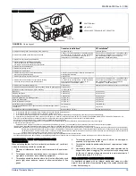
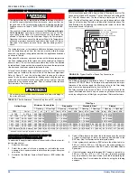
FIGURE 5:
Side Return Cutout Markings
FRONT OF
FURNACE
CORNER
MARKINGS
All installations must have a filter installed.


