8
FURNACE SIZING AND DUCT SYSTEM
DESIGN
The duct system must be installed in conformance
with ASHRAE/NFPA 90, Standard for Installation of
Warm Air Heating and Air Systems and other
applicable local codes. Failure to adhere to proper
duct system design standards can reduce airflow,
resulting in reduced system performance and
possible furnace damage.
Consideration should be given to the heating
capacity required and also to the air quantity (CFM)
required if A/C is to be installed along with the
furnace or at some future time. These factors can be
determined by calculating the heat loss and heat
gain of the home or structure.
If these calculations are not performed and the
furnace is oversized, the following may result:
1. Short cycling of the furnace.
2. Wide temperature fluctuations from the thermo-
stat setting.
3. Reduced overall operating efficiency of the
furnace.
The supply and return duct system must be of
adequate size and designed such that the furnace
will operate within the designed air temperature rise
range and not exceed the maximum designed static
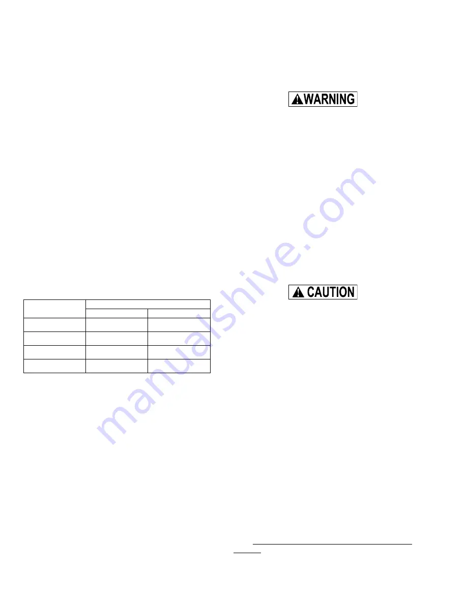
pressure. These values are listed in the table below.
EXT. STATIC IN. W.C.
INPUT BTUH
MINIMUM
MAXIMUM
50,000
.10
.50
75,000
.12
.50
100,000
.15
.50
125,000
.20
.50
Additional information, values and data necessary
for heat loss, heat gain and duct system design may
be found in the ASHRAE HANDBOOK OF FUNDA-
MENTALS or in other nationally recognized publica-
tions recognized by municipal, state, provincial and
federal code authorities.
If possible, it is recommended that the supply air
duct attached to the furnace be provided with a
removable access panel. The opening should be
accessible when the furnace is installed in service
and should be large enough that smoke or reflected
light may be observed inside the casing to indicate
the presence of leaks in the heat exchanger. The
cover panel for this opening should be attached in
such a manner as to prevent leaks.
A/C Usage Duct Systems
1. When a single (common) duct system is used,
one of the following methods shall be used:
a. A plenum type cooling coil must be installed
on the air discharge side, or
b. A blower-coil type cooling coil must be in-
stalled in parallel with and isolated from the
furnace, or
c. A self-contained A/C unit must be in parallel
with and isolated from the furnace.
Dampers must be installed when coil-blower
or self-contained unit is employed to pre-
vent conditioned cool air from coming in
contact with the heat exchanger to avoid
moisture condensation and rust-out. This
can allow products of combustion to be cir-
culated into the living area by the furnace
blower resulting in possible asphyxiation. If
dampers are of a manually operated type, a
means must be provided to prevent either
the furnace or A/C unit from operating un-
less dampers are in full heat or cool posi-
tion.
If two duct systems are used as could be the case
with a coil-blower or a self-contained A/C unit, the
furnace and A/C unit should be controlled by a
single combination heating and cooling thermostat
which will prevent the furnace and A/C unit from
operating simultaneously.
If a separate heating and separate cooling
thermostat is used, a manually operated
electrical interlock switch must be installed
to prevent simultaneous operation of both
systems and to avoid a possible hazardous
condition due to overheating of the condi-
tioned space.
RETURN AIR AND FILTERS
Return Air Temperature
This furnace design is to be operated in normal
household temperatures. The continuous return air
temperature must not be below 60°F or above 85°F.
Return Air Connection – Upflow
The return air may be brought in through the bottom
of the furnace or through one or both sides of the
furnace casing. The furnace casing may be cut out
so that side return air connections may be used. The
furnace is supplied with flanges on the top of the
furnace to which the return air duct may be fastened.
The casing top is embossed to indicate where to
bend the flanges. If a side return is to be used, cut
out the side of the casing 14" high by 16 1/4" wide
using the lances in the casing side as a guide. DO
NOT CUT THE OPENING LARGER THAN 14"x 16
1/4". It is not permissible to cut out the back of the
furnace.
Содержание G8C 50
Страница 11: ...11 FIGURE 9 DOWNFLOW CONFIGURATION FIGURE 10 UPFLOW CONFIGURATION ...
Страница 23: ...23 ...


