- 13 -
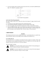
F. Connect the negative polarity of the device being powered to the black (-) terminal of the MASTER power
supply. The configuration is as shown in Fig.5-5.
Fig.5-5 Parallel Tracking Operation
5-4-4. Fixed 5V Power Supply Operation
The fixed 5V supply provides a 5V DC output with a 3 amp current capacity. The supply is ideal for use with
TTL circuits.
A. Turn off the power supply and the equipment to be powered during hook-up.
B. Connect the polarity the device being powered to the red (+) terminal of the 5V supply.
C. Connect the negative polarity of the device being powered to the black (-) terminal of the 5V supply.
D. If the red OVERLOAD indicator lights, too much load has been placed on the supply. This will cause
voltage and current to drop and prevent proper operation of the 5V supply. To correct this situation, the
load on the supply must be decreased so that no more than 3 amps of current are sucked.
6. MAINTENANCE
WARNING
The following instructions are for use by qualified personnel only. To avoid electrical shock, do not perform any
servicing other than contained in the operating instruction unless you are qualified to do so.
6-1. Fuse Replacement
If the fuse blows, the CV or CC indicators will not light and the power supply will not operate. The fuse shall
not normally open unless a problem has developed in the unit. Try to determine and correct the cause of the
blown fuse, then replace only with a fuse of the correct rating type.
The fuse is located in rear panel.
WARNING.
For continued fire protection, replace fuse only with 250V of the specified type and
rating. And disconnect the power cord before replacing fuse.
WARNING.
To protect the transformer and circuits of the unit, a fuse of the correct rating and
type must be used. Refer to below for correct fuse ratings.

