22
6
EXTERNAL INPUT/OUTPUT SIGNALS
22
EX
TERNAL INPUT/OUTPUT S
IGNAL
S
Chapter
6
6-1.
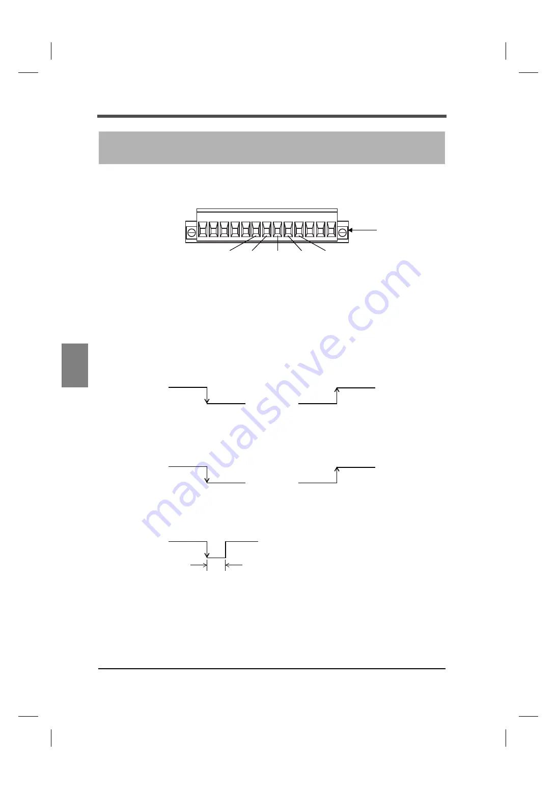
Connector pin assignments
6-2.
External input signals
IN1: Hold/Judge
IN2: Digital zero
■
Hold/Judge <edge input>
For hold signal, please use hold mode.
When the hold mode is OFF, it operates as a judgment signal of comparison timing.
However, it is unrelated when comparison timing condition is ALWAYS or NZ.
■
Digital zero <edge input>
The digital zero works to zero the indicated value.
6
EXTERNAL INPUT/OUTPUT SIGNALS
Signal input/output
6 7 8 9 10
IN1
IN2
OUT1 OUT2
7
8
9
10
COM
6
terminal block
OFF
Hold ON
ON
OFF
Hold OFF
ON
OFF
Judge ON
ON
OFF
Judge OFF
ON
OFF
ON
Pulse width 50mSec or more
Содержание F331
Страница 1: ...OPERATION MANUAL 26MAY2014REV 1 02 DIGITAL INDICATOR F331 ...
Страница 79: ...70 8 SPECIFICATIONS 70 SPECIFICATIONS Chapter 8 8 2 Dimensions Unit mm ...
Страница 80: ...71 8 SPECIFICATIONS 71 SPECIFICATIONS Chapter 8 When the BCD output option is equipped Unit mm ...
Страница 81: ...72 8 SPECIFICATIONS 72 SPECIFICATIONS Chapter 8 When the D A converter option is equipped Unit mm ...
Страница 82: ...73 8 SPECIFICATIONS 73 SPECIFICATIONS Chapter 8 When the RS 485 option is equipped Unit mm ...
Страница 83: ...74 8 SPECIFICATIONS 74 SPECIFICATIONS Chapter 8 When the RS 232C option is equipped Unit mm ...


