14
PCM500 SERIES
OPERATING MANUAL
This table shows that, for example, a 50mV, 100A shunt is the shunt resis-
tance that produces 50mV for a 100A full-scale current. In this case the
shunt resistance is 50mV ÷ 100, or 0.5 milliohm. The shunt rating is always
the full-scale current that produces 50mV across the shunt.
The 3 ½ digit ammeter resolves current readings to 0.1A over the 25A to
200A full-scale range. From 250A to 2000A full scale, the meter resolves
current to the nearest ampere. Overall accuracy is moderate, generally within
±5%. Current may also be measured at the “AMPS” test points by using a
50mV full scale voltmeter. The external shunt must be also used for this
measurement. The actual current must then be determined by multiplying the
meter reading in millivolts by the full scale shunt current divided by 50.
16.0
BATTERY TEMPERATURE COMPENSATION
16.1
The temperature compensation option (Option TC) comes with a temperature
probe and 20-foot cable. The probe is a thermistor which is connected to TB1
pins 9 and 40. There is no polarity for this connection. The probe is used to
monitor the temperature of the battery and adjust the rectifier output voltage
accordingly. As battery temperature increases, rectifier output voltage de-
creases.
16.2
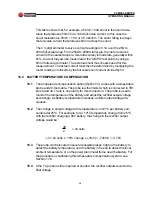
The change in output voltage with temperature is -3mV/ºC per battery cell,
centered at 25ºC. For example, for a +10ºC temperature change from 25ºC
with the rectifier charging a 48V battery, the change in the rectifier output
voltage would be:
48
2
r
V = 24 cells x 10ºC change x (-3mV) = -720mV = -0.72V
16.3
The probe can be located in several possible places: right on the battery to
detect the battery temperature; near the battery in free air to detect the local
ambient temperature; or on the power plant metal frame near the battery. For
the procedure on calibrating this temperature compensation system, see
Section 17.6.
16.4
If the TC probe is either opened or shorted, the rectifier outputs revert to the
float voltage.
= 24 cells


