background image

10

PCM500 SERIES

OPERATING MANUAL

Outputs on terminals 13-36 are Form C relay contact alarms for the functions
given. “Normally Closed” (NC) means a “short” between this terminal and the
Common (C) terminal when the function is operating properly with power
applied. “Normally Open” (NO) means an “open” between this terminal and
the Common (C) terminal when the function is operating properly with power
applied.

13.3

Abbreviations/Acronyms. These are used in the previous tables and are
defined in the following table.

13.4

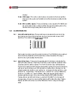
Explanation of Other I/O Connections. Most of the connections to TB1 are
alarm inputs and outputs. The “Other I/O” connections are various analog
type connections.

13.41 I+ and I- Input. These are the + and - connections from a meter shunt

that is used to measure battery current. See Section 15.3 on
“Current” for further details.

13.42 TC Input. This is the optional temperature compensation input from

the temperature compensation probe that comes with this option. The
probe is used to measure battery temperature which is used to control
the output of the rectifier. See Section 16.0 on “Battery Temperature
Compensation”. There is no polarity reference on this.

13.43 B+ and B- Input. These connections are to the common rectifier

output bus which is used to provide power to operate the PCM500

ACRONYM

                      DESCRIPTION

LVDA

Low Voltage Disconnect Alarm

FA

Fuse/Circuit Breaker Alarm

I+, I-

Meter Shunt

TC

Temperature Compensation  (from probe)

B+, B-

Battery (from rectifier bus)

CS

Current Share (to rectifier shelves)

EQA

Equalize Alarm

OVA

Battery Overvoltage Alarm

RFA-MIN

Rectifier Failure Alarm - Minor (single rectifier failure)

ACFA

AC Failure Alarm

RFA-MAJ

Rectifier Failure Alarm - Major (two or more
rectifier  failures)

UVA

Battery Undervoltage Alarm

RA

Remote Adjust (to rectifier shelves)

BS+, BS-

Battery Sense

Содержание PCM500 Series

Страница 1: ...controller is in the optional equalize voltage mode Front panel red LEDs give the following alarms rectifier fail alarm minor indicating a single rectifier failure rectifier fail alarm major indicati...

Страница 2: ...nd 4 24V Neg Gnd Model No PCM500 CODE OPTION EV EQUALIZE VOLTAGE MODE MP METER PANEL TC BATTERY TEMP COMPENSATION 25 25A 30 30A 50 50A 75 75A 100 100A 150 150A 200 200A 250 250A 300 300A 500 500A 1000...

Страница 3: ......

Страница 4: ...Rights Reserved UNIPOWER Telecom Division of UNIPOWER Corporation 01 14 02 PCM500 Man NORTH AMERICA 3900 Coral Ridge Drive Coral Springs Florida 33065 USA Tel 1 954 346 2442 Fax 1 954 340 7901 sales u...

Страница 5: ...Standards 5 8 0 Front Panel Description 5 9 0 Back Panel Description 6 10 0 LED Indicators 6 11 0 Front Panel Adjustment Potentiometers 6 12 0 Description of Operation 7 13 0 Connections 7 14 0 Alarm...

Страница 6: ...URE TITLE PAGE 1 PCM500 Power Control Monitoring System 2 2 Front and Back Panels of PCM500 2 3 PCM500 Functions 8 4 Current Measurement Connections 13 5 Test Setup for Setting Battery Overvoltage and...

Страница 7: ...tatus and alarms 1 4 The PCM500 is only one mounting position high 1 75 inches to minimize rack space and comes with brackets that permit mounting in either a 19 or 23 inch relay rack It can be mounte...

Страница 8: ...500 SERIES OPERATING MANUAL Figure 1 PCM500 Power Control Monitoring System Figure 2 Front and Back Panels of PCM500 FRONT VIEW REAR VIEW RECTIFIER SHELF CONNECTORS ALARM ENABLE DIP SWITCHES TB1 CONNE...

Страница 9: ...ty does not extend to products which have been opened altered or repaired by persons other than persons authorized by the manufacturer or to products which become defective due to acts of God negligen...

Страница 10: ...ing material as evidence of damage for the freight carrier s inspection 5 3 UNIPOWER Telecom will cooperate fully in case of any shipping damage investigation 5 4 Always save the packing materials for...

Страница 11: ...to indicate conformance to the European Union s Low Voltage Directive 8 0 FRONT PANEL DESCRIPTION 8 1 On the left side of the front panel are the digital voltmeter and digital ammeter These meters fo...

Страница 12: ...tputs and other input output connections These terminals accept AWG nos 14 to 22 wire sizes 10 0 LED INDICATORS 10 1 Yellow LED Indicates controller is in the equalize voltage mode option determined b...

Страница 13: ...nd up to five fuse panels or circuit breaker panels The alarm outputs are Form C relay contacts which can be used for remote or local system alarms The PCM500 has inputs from the low voltage disconnec...

Страница 14: ...8 PCM500 SERIES OPERATING MANUAL Figure 3 PCM500 Functions FUSE CIRCUIT BREAKER PANELS RECTIFIER SHELVES...

Страница 15: ...VDA NC 24 TB1 TERMINAL CONNECTIONS NOTE J1 J4 Connectors are for rectifier shelves 1 4 respectively Numbers following functions refer to rectifier modules 1 4 in each shelf NC No connection 14 25 13 1...

Страница 16: ...on Current for further details 13 42 TC Input This is the optional temperature compensation input from the temperature compensation probe that comes with this option The probe is used to measure batte...

Страница 17: ...ch to the right enables that function 14 2 Alarm Functions There are 24 separate alarm functions controlled by the Alarm Enable switches Only those functions used should be enabled other wise false al...

Страница 18: ...lts test points on the right front panel also permit direct external measurement of the battery voltage when the MP option is not taken 15 3 Current The digital ammeter is scaled at the factory to rea...

Страница 19: ...13 PCM500 SERIES OPERATING MANUAL Figure 5 Test Setup for Setting Battery Overvoltage and Undervoltage Figure 4 Current Measurement Connections...

Страница 20: ...sation option Option TC comes with a temperature probe and 20 foot cable The probe is a thermistor which is connected to TB1 pins 9 and 40 There is no polarity for this connection The probe is used to...

Страница 21: ...here the UVA undervoltage alarm red LED just turns on Turn off the 0 60V supply and disconnect it 17 4 Setting the Battery Float Voltage Connect a single rectifier to the PCM500 by means of J1 Set the...

Страница 22: ...Move the SR33 DIP switch to the enable position The RFA MIN and ACFA red LEDs should again turn on Move the SR44 DIP switch to the enable position The RFA MAJ rectifier failure alarm major red LED sh...

Страница 23: ...e Form C relay outputs Normally Closed NC means a short between this terminal and the common C terminal when the function is operating properly with power applied Normally Open NO means an open betwee...

Страница 24: ...39 and 38 respectively to the positive and negative sides of the battery but on the rectifier side of any battery disconnects or circuit breakers 18 10 The PCM500 is now ready to operate The shunt sh...

Отзывы: