background image

C.I.B. U

N

IGAS

 - M0391

36CC

27

Содержание IDEA Series

Страница 1: ...MANUAL OF INSTALLATION USE MAINTENANCE LO60 LO90 IDEA series Light oil burners M039136CC Rev 2 04 2008 BURNERS BRUCIATORI BRULERS BRENNER QUEMADORES...

Страница 2: ...Connecting the light oil flexible hoses 12 ADJUSTMENTS 14 Adjusting the fuel flow rate 14 Priming the pump 15 Priming the pump for single stage burners 15 Priming the pump for double stage burners 15...

Страница 3: ...ins electricity gas oil or other fuel z Observe caution with hot burner components These are usually near to the flame and the fuel pre heating system they become hot during the unit operation and wil...

Страница 4: ...f toxic or explosive mixtures DIRECTIVES AND STANDARDS Gas burners European directives Directive 90 396 CEE Gas Appliances Directive 2006 95 EC on low voltage Directive 2004 108 CEE on electromagnetic...

Страница 5: ...ntrol box for safety reasons one controlled shutdown must take place every 24 hours z Burners provided with Siemens LMO24 44 control box the control box automatically stops after 24h of continuous wor...

Страница 6: ...307 304 14 291 80 98 145 218 M8 153 96 120 108 2 291 LO60 Extended 443 58 169 274 385 304 14 291 80 98 145 218 M8 153 96 120 108 2 291 LO90 Standard 365 58 71 294 307 304 14 291 80 98 145 218 M8 153 9...

Страница 7: ...ON CHAMBER mbar LO60 G TN kW LO60 G AB kW PRESSURE IN COMBUSTION CHAMBER mbar LO90 G TN kW LO90 G AB kW 0 0 5 1 1 5 2 2 5 3 20 30 40 50 60 70 0 0 5 1 1 5 2 2 5 3 20 30 40 50 60 70 0 0 5 1 1 5 2 2 5 3...

Страница 8: ...dimensions 2 fix the flange of the burner to the boiler 3 install the burner into the boiler 4 according to the reference showed on Fig 2 fix the flange to the boiler s stud bolts D without completely...

Страница 9: ...y the chapter WARNINGS and the Electrical connections section WARNING the burner is fitted with a bridge between terminals T6 and T8 on CN2 TAB connector external side link male connector remove this...

Страница 10: ...the use of fuel pumps z Make sure that the by pass plug is not used in a single pipe installation because the fuel unit will not function properly and damage to the pump and burner motor could result...

Страница 11: ...for ced circulation feed systems If the device installed is a solenoid valve a timer must be installed to delay the valve closing The direct connection of the device without a timer may cause pump br...

Страница 12: ...600 rpm Key Suntec AS47 1 Pressure governor 2 Pressure gauge port G1 8 3 Vacuum gauge port G1 8 4 Solenoid valve 5 Delivery to nozzle G1 8 7 Inlet G1 4 8 Return G1 4 Key Suntec AT2 45A 1 Low pressure...

Страница 13: ...l on the flexible light oil hoses and the power cord as shown in the figure while also re assem bling the cable clamp plate P in Fig 11 Fig 10 Insert the rubber seal in its seat in the burner volute a...

Страница 14: ...he following chart Recommended combustion parameters Fuel Recommended CO2 Recommended O2 Light oil 11 5 13 2 9 4 9 Note all pumps are set to 12 bar The nozzle rate must be higher than the rate referre...

Страница 15: ...the burner locks press the unlock pushbutton placed on the upper side of the burner and repeat the steps above 10 The oil flow rate depends on the choosen nozzle 11 Checking the combustion values adju...

Страница 16: ...h flame by means of the thermostat TAB if TAB is not present insert a bridge between T6 and T8 contacts on the related connector see page 9 12 adjust the high flame air flow rate acting on the related...

Страница 17: ...IN position rotating the VR screw clockwise Fig 20 Combustion setting Tab 3 LO60 Tab 4 LO90 BERGER STA4 5BO 37 Air adjustment in high flame cam I Air adjustment in low flame Stand by Ignition cam II A...

Страница 18: ...AND SAFE FUNCTIONING OF THE BURNER THEREFORE ANY OPERATION OF THE APPLIANCE MUST BE PREVENTED WHICH DEPARTS FROM THE INSTALLATION OPERATIONS OR WHICH HAPPENS AFTER TOTAL OR PARTIAL TAMPERING WITH THE...

Страница 19: ...on for a few seconds after the ignition of the flame post ignition time after which it is disconnected from the circuit Double stage burners 1 Set Switch G on the burner control panel in ON position 2...

Страница 20: ...insulators clean adjust and replace if necessary z Disassemble and clean the light oil nozzles IMPORTANT cleaning must be performed using solvent not metal tools At the end of maintenance operations a...

Страница 21: ...ing 4 adjust the electrodes to replace them if necessary disconnect the cables and unscrew the electrodes fixing screw 5 clean the combustion head by means of a vacuum cleaner use a metallic brush to...

Страница 22: ...onal stop To stop the burner in the seasonal stop proceed as follows 1 turn the burner s main switch to 0 Off position 2 disconnect the power mains 3 close the fuel cock of the supply line Burner s di...

Страница 23: ...the components plate and the burner cover Before disassembling the nozzle measure the real position A see Fig 26 and make a note in the table below ATTENTION check that the factory set values are obs...

Страница 24: ...ATION MAINS SWITCH OPEN z FUSES INTERVENTION z MAXIMUM PRESSURE SWITCH FAULT z z AUXILIARIES RELAY FUSES INTERVEN TION z CONTROL BOX FAULT z z z z z SERVOCONTROL FAULT z SMOKY FLAME z z IGNITION TRANS...

Страница 25: ...ER COFI 2170139 2170139 2170139 2170139 IGNITION TRANSFORMER DANFOSS 2170231 2170231 2170231 2170231 ELECTRIC MOTOR 2180713 2180713 2180713 2180713 SOLENOID VALVE 2190638 2190638 2190638 2190638 FLEXI...

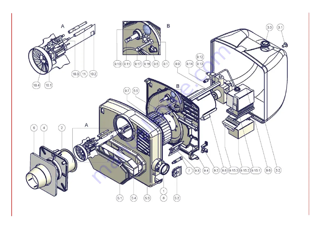
Страница 26: ...T 7 1 AIR DAMPER ADJUSTING SCREW 8 1 DAMPER SHAFT 9 1 1 NUT 9 2 1 FAIRLEAD 9 3 1 AIR INTAKE DAMPER 9 4 1 MOTOR SUPPORT PLATE 9 5 1 FAIRLEAD 9 6 1 CONTROL BOX 9 7 1 FAN WHEEL 9 8 1 MOTOR 9 9 1 PIN 9 10...

Страница 27: ...C I B UNIGAS M039136CC 27...

Страница 28: ...power supply terminal board MV Fan motor SATRONIC DKO976 DKW976 DKW976 Contrl box N Neutral ST Thermostats or pressure switches STA4 5B0 37 63N21L Air damper actuator TA Ignition transformer TS Thermo...

Страница 29: ......

Страница 30: ......

Страница 31: ......

Страница 32: ......

Страница 33: ...ssure with a screw driver in the slot of the mounting guide The base dimensions of the socket are exaclty the same as for types LAB LAI and there is no difference in the diameter of the reset button t...

Страница 34: ...ty solenoid external light short circuit in the photoresisto or wiring malfunction in the flame signal amplifier etc at the end of pre purge and safety time the controller locks out the burner and sto...

Страница 35: ...is restarted each time controlled switching on by R W SB takes place Operation Lock out reset button EK is the key operating element for resetting the burner control and for activating deactivating t...

Страница 36: ...s using no oil pre heater Controller output signals Required input signals OH Oil pre heater QRB Photoresistive detector QRC Blue flame detector bl blue br brown sw black R Control thermostat or press...

Страница 37: ...Max perm amperage at cos 0 6 LMO14 LMO24 LMO44 Terminal 1 5 A 5 A Terminals 3 and 8 3 A 5 A Terminals 4 5 6 and 10 1 A 1 A Flame supervision with QRB and QRC QRB QRC Min detector current required wit...

Страница 38: ......

Страница 39: ......

Страница 40: ...and data subject to change Errors and omissions excepted C I B UNIGAS S p A Via L Galvani 9 35011 Campodarsego PD ITALY Tel 39 049 9200944 Fax 39 049 9200945 9201269 web site www cibunigas it e mail...

Отзывы: