
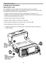
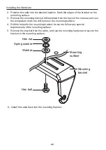
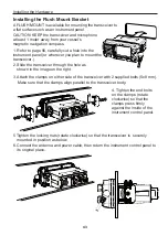


Installing the Hardware
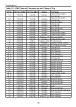
46
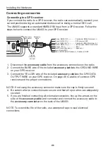
Connecting accessories
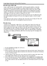
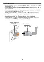
Connecting to a GPS receiver
If you connect the radio to a GPS receiver, the radio can automatically transmit your
current position during an automated distress call or during a normal DSC call.
The UM455 supports a standard NMEA0183 input from a GPS receiver. Follow the
steps below to connect the UM455 to your GPS receiver:
1. Disconnect the
accessory cable
from the accessory connection on the radio.
2. Connect the BARE wire of the included
accessory cable
to the GROUND WIRE
on your GPS receiver.
3. Connect the YELLOW wire of the included
accessory cable
to the GPS DATA
OUTPUT WIRE on your GPS receiver. On page 46 is a table of common GPS
receivers and the proper connections:
NOTE: If not using the accessory connector make sure the cap is fi rmly secured.
4. Be certain all wire connections are secure and that all open wires are adequately
covered.
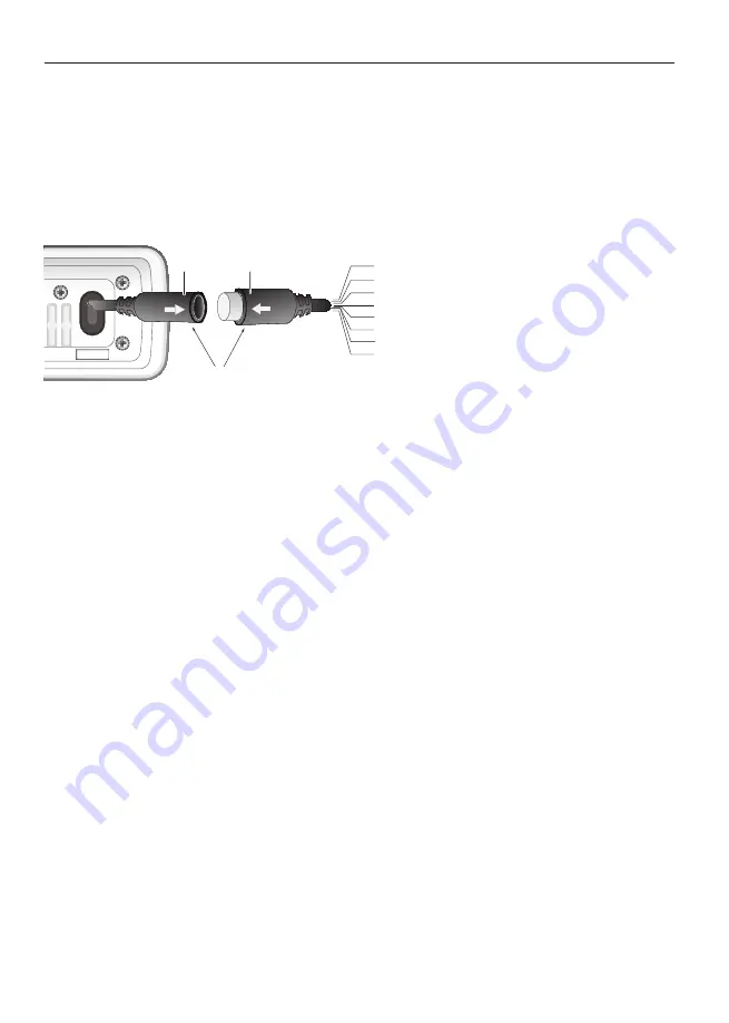
5. If you are finished connecting all external accessories, line up the arrows on the
side of the
accessory cable
and connector and connect the accessory cable to
the
accessory connector
on the back of the UM455.
NOTE: To extend the life of the radio, use waterproof tape to seal electrical
connections.
13.8V DC
Accessory
cable
Accessory
connector
White: NMEA OUT (+)
Orange: PA (+)
Green: NMEA IN (-)
Yellow: NMEA IN (+)
Red: External Speaker (+)
Bare: Shield/GND
Brown: NMEA OUT (-)
Black: GND/External Speaker(-)
Line up
arrows to
connect
............Chartplotter NMEA Data Input (-)
................GPS receiver GND
..............Chartplotter NMEA Data Input (+)
................GPS receiver NMEA Data Output
.........................PA(+)
........S)
...Speaker(-)/GND


