
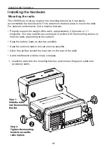
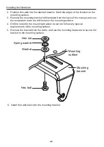


Installing the Hardware
44
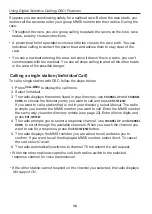
Connecti ng the radio
To operate correctly, your UM455 requires two electrical connections:
•
providing it with power from the boat’s electrical system
•
connecting a VHF-FM marine antenna to the antenna connector
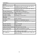
Power supply requirements
VHF antenna requirements
Nominal 13.8 VDC power supply with
a negative ground (10.8 VDC to 15.6
VDC).
Power leads should be kept as short
as possible. A direct connection to the
power supply is ideal.
Minimum of #14 AWG copper wire for
extensions up to 6m, 12 AWG wire for
extensions from 6m to 10m, or 10 AWG
wire for extensions from 10 to 18m
Male PL-259 connector
50 Ω impedance
Minimum 1.2m, 3 dB rated antenna for
sailboats or 2.4m, 6dB rated antenna for
powerboats
Minimum RG-58 lead-in wire for antenna
leads up to 6m to 10m, RG-8X for an-
tenna leads from 6m to 10m, or RG-8U
for antenna leads from 10m to 18m.
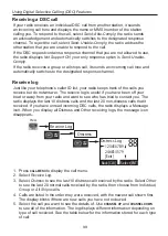
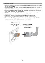
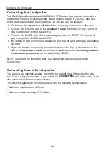
13.8V DC
Power
cable
Power
connector
Black wire
(-)
Red wire
(+)


