background image

-  13  -

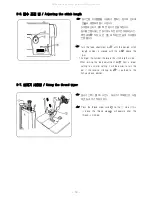
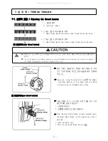
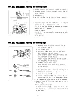
7-2. 사절 후 윗실 잔사량 조절법 / Adjusting the trailing length after thread trimming


☞ 

프리텐션① 조정에 의한 조절.


▷ 

사절  타이밍  시  실의  장력은  느슨해야  되며,  실의     

        장력은 프리텐션에 의한 장력의 힘만 가지고 있어야  

        합니다.


▷ 

사절시  윗실의  적절한  잔사의  량은  35-40㎜가  적당   

        합니다.


▷ 

만일 프리텐션①의 장력이 증가되면 바늘에 남아 있는  

       잔사의 양이 줄어들며, 프리텐션①의 장력이 감소되면  

       잔사의 양이 늘어납니다.


 Adjust by turning the pretension①.


▷ 

At  the  time  of  thread trimming,  the  thread tension   

        loosened  and  tension  is  applied  by  the  pretension   

        only.


▷ 

The standard trailing length for the upper thread is a  

                                                         35-40㎜.


▷ 

If  the length  of the  pretension①  is  increased,  the    

                                                         length of the thread trailing from the needle tips will  

                                                         be reduced. if the tension is reduced, the lengths will  

                                                         increased.

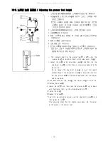
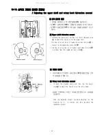
7-3. 노루발  압력 조절법 / Adjusting the presser foot pressure


☞ 

노루발  압력은  부드러운게  좋다.  그러나  재봉천이   

        미끄러지지 않을 정도로는 충분히 강해야 한다. 


1. 조절너트①를 풀어준다. 

    2. 조절나사를 돌려가며 노루발 압력을 조절한다. 

    3. 조절너트①를 체결한다. 


☞ 

The presser  foot pressure  should be as  weak as   

        possible, but strong enough so that the material  

        does not slip.

    1. Loosen the adjustment nut①.

    2.  Turn  the  adjustment  screw to  adjust the presser   

       foot pressure.

    3. Tighten the adjustment nut①.

All manuals and user guides at all-guides.com

Содержание DB2-H515

Страница 1: ...SINGLE NEEDLE ULTRA HIGH SPEED LOCKSTITCH SEWING MACHINE WITH THREAD TRIMMER 1 OPERATION MANUAL PART BOOK DB2 H515 LS2 H5150 All manuals and user guides at all guides com a l l g u i d e s c o m...

Страница 2: ...All manuals and user guides at all guides com...

Страница 3: ...eware of injury This symbol indicates something that you must not do This symbol indicates something that you must do The picture inside the circle indicates the nature of the thing that must be done...

Страница 4: ...5 off A S 31 2 40 25 OFF A S A S All manuals and user guides at all guides com...

Страница 5: ...bend the cable or secure it too firmly staples otherwise shocks could occur install the belt covers to the machine head and motor Be sure to wear protective goggles and gloves when handling the lubric...

Страница 6: ...the machine and when leaving the machine unattended If an error occurs in machine operation or if abnormal noises or smells are noticed immediately turn off the power switch Then contact your nearest...

Страница 7: ...maintenance and inspection of the electrical system Turn off the power switch and disconnect the power cord from the wall outlet at the following times otherwise the machine may operate if the treadle...

Страница 8: ...ase contract your nearest UNICORN dealer The positions of the labels may vary slightly depending on the model of sewing machine or motor 1 2 Be sure to connect the ground If the ground connection is n...

Страница 9: ...rned on verify the rotational direction of the pulley with the power on The pulley should rotate counterclockwise when viewed from the pulley Power must be turned off when the machine is not in use or...

Страница 10: ...2 Backtacking 11 7 THREAD TENSION 12 1 Adjusting the thread tension 12 2 Adjusting the trailing length after thread trimming 13 3 Adjusting the presser foot pressure 13 8 CLEANING 14 9 REPLACING THE...

Страница 11: ...LE TYPE DB x 1 11 DB x 1 22 19 23 STITCH ADJUSTMENT DIAL LUBRICATION SYSTEM AUTOMATIC BED DIMENSIONS 476 x 178 mm THREAD TRIMMER SYSTEM STANDARD STANDARD STANDARD WIPER SYSTEM STANDARD STANDARD STANDA...

Страница 12: ...ore than 31kg The installation should be carried out by two or more people Do not connect the power cord until installation is complete otherwise the machine may operate if the treadle is depressed by...

Страница 13: ...work table so that corners are aligned 4 2 4 Insert the two rubber cushions into the notches in the 5 5 Insert the knee lifter complying bar 4 2 Installing the knee lifter assembly 1 1 Place the knee...

Страница 14: ...approximately 2mm when the knee lifter plate is gently pressed 5 Securely tighten the nut 6 Loosen the nut 7 Turn the screw until the distance between the end of the screw and the knee lifter is appro...

Страница 15: ...so that it pushes the belt by approximately 5mm and then place the bobbin winder so that it is parallel with the belt hole in the work table 3 Install the bobbin winder to the work table with the two...

Страница 16: ...stand 1 1 Assemble the cotton stand and then install the cotton stand to the far right corner of the work table Securely tighten the nuts so that the rubber cushion and the washers are securely clamp...

Страница 17: ...he screw 3 Insert the needle in a straight line as far as it will go making sure that the long groove on the needle is at the left and then securely tighten the screw 5 2 Removing the bobbin case 1 2...

Страница 18: ...ding of the lower thread is completed the bobbin presser arm will return automatically 8 Remove the bobbin and trim the thread as shown in the illustration If the thread cannot be wound on evenly loos...

Страница 19: ...is above the needle plate 2 While holding the bobbin so that the tread winds to the right insert the bobbin into the bobbin case 3 Pass the thread through the slot and under the tension spring and the...

Страница 20: ...gth will be When turning the feed adjustment dial from a larger setting to a smaller setting it will be easier to turn the dial if the reverse stitching lever is pushed to the half way down position 5...

Страница 21: ...bin When not using the machine and when leaving the machine unattended Do not touch any of the moving parts or press any objects against the machine while sewing as this may result in personal injury...

Страница 22: ...n too strong 3 Upper thread tension too strong or lower thread tension too weak Lower thread tension Adjust by turning the adjustment screw the bobbin case drops gently by its own weight while the thr...

Страница 23: ...of the pretension is increased the length of the thread trailing from the needle tips will be reduced if the tension is reduced the lengths will increased 7 3 Adjusting the presser foot pressure 1 2...

Страница 24: ...3 Use a soft wire brush to clean any dust from the feed dog 4 Install the needle plate with the two screws 5 Tilt back the machine head 6 Remove the bobbin case 7 Wipe off any dust from the rotary hoo...

Страница 25: ...rew and then remove the fixed knife Carry out the above steps in reverse to install the fixed knife Sharpening the fixed knife If the knifes become blunt sharpen the fixed knives as shown Replacing th...

Страница 26: ...operate if the treadle is pressed by mistake which could result in injury When carrying out inspection adjustment and maintenance When replacing consumable parts such as the rotary hook If the power s...

Страница 27: ...on of the thread tension spring If using a tension gauge sold separately measure the tension take the reading from the scale on the side of the red line 10 2 Adjusting arm thread guide R ARM R R 1 R 2...

Страница 28: ...tment screw is loosened more than this the presser bar will become separated from the presser foot spring guide 2 Raise the presser bar lifter lever The presser foot will also rise 3 Remove the oil ca...

Страница 29: ...90 4 1 Turn the machine pulley to move the feed dog to its highest position above the needle plate 2 Loosen the two set screws 3 Turn the feed bracket shaft in the direction of the arrow within a ran...

Страница 30: ...rom its lowest position until the lowest reference line from the bottom of the needle bar is aligned with the bottom edge of needle bar bush as shown in the illustration 1 Set the feed adjustment dial...

Страница 31: ...g The vertical cam and horizontal cam are linked by a pin so that if either one is turned the other will turn with it To advance the needle timing turn in the direction of To retard the needle timing...

Страница 32: ...is alilgned with the belt cover reference there should be a 12 5 to 15 mm gap between the needle plate top and needle tip 1 2 3 4 Needle up stop position adjustment 1 Turn off the power switch 2 Loos...

Страница 33: ...he mark is closest to the needle bar crank shaft The flow of oil will be at its highest level when the mark is furthest from the needle bar crank shaft Rotary hook lubrication amount Tilt back the mac...

Страница 34: ...24 7 7 20 20 20 10 9 7 7 12 12 16 23 All manuals and user guides at all guides com...

Страница 35: ...ad wiper too high Thread wiper position Adjust thread wiper position with screw 10 Thread breakage Improper threading Threading Rethread 9 Bent needle Blunt needle tip Jammed eye Needle Replace needle...

Страница 36: ...26 7 7 1 7 9 20 20 20 13 16 All manuals and user guides at all guides com a l l g u i d e s c o m...

Страница 37: ...pressure Tighten presser foot adjustment screw Presser bar height Adjust presser bar height Improper needle to rotary hook timing Needle bar rise Adjusting the rotary hook timing 20 Needle bar height...

Страница 38: ...28 12 12 12 12 puff 20 7 15 15 15 All manuals and user guides at all guides com...

Страница 39: ...Adjusting the rotary hook timing 20 Improper thread cutting a Needle bobbin threads not cut b Needle thread not cut c Bobbin thread not cut Movable knife fixed knife do not overlap Adjust knives Movab...

Страница 40: ...30 13 1 13 All manuals and user guides at all guides com...

Страница 41: ...ion timing Thread cutter mechanism does not function Thread cutter solenoid dose not function Check with tester Replace thread cutter solenoid Thread cutter signal not transmitted Check circuits refer...

Страница 42: ...32 All manuals and user guides at all guides com...

Отзывы: