Electronic System
- 50 -
5.3 Sampling and Signal Processing System
The working principle as follow:
1. The photo-detector receives the light signal, converts it to be electrical signal
(analog signal);
2. Amplifier the analog signal, the multiple is control by the CPU on the Slave
CPU PCB (W78E52B);
3. The A/D converts analog signal to be digital signal;
4. The Slave CPU send the digital signal to the main CPU.
5.3.1 Amplifier
PCB(SST8.413.104A)
The layout of the Amplifier PCB of UV-2800, UV-2802, UV-2802PC,
UV-2802S and UV-2802PCS (R17—R20 of UV-2802S and UV-2802PCS are
different from others) is shown in figure 5.18, UV-4802 is shown in figure
5.19:
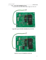
Figure 5.18 Layout of UV-2800, UV-2802, UV-2802S,
UV-2802PC, UV-2802PCS, UV-3802 Amplifier PCB
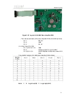
The sockets description of the Amplifier PCB of UV-2800, UV-2802(S),
UV-3802 as follow:
J1---From Power Distributing PCB
Pin
1:
DC
+9V
Pin
2:
GND
Pin
3:
DC
-9V
J2---From Slave CPU PCB
Содержание SQ Series
Страница 5: ......
Страница 8: ...Introduction 3 Figure 1 5 Model UV 4802...
Страница 12: ...Layout 7 Figure 3 2 Layout of UV 2800 Inside Bottom View...
Страница 13: ...Layout 8 39 40 41 42 43 Figure 3 3 Layout of UV 2800 Top View...
Страница 14: ...Layout 9 230V 44 45 46 47 48 49 50 51 Figure 3 4 Layout of UV 2800 Back View...
Страница 18: ...Layout 13 Figure 3 7 Layout of UV 2802 S UV 2802PC S Inside Bottom View...
Страница 19: ...Layout 14 43 44 45 46 47 Figure 3 8 Layout of UV 2802 S Top View...
Страница 20: ...Layout 15 230V Figure 3 9 Layout of UV 2802 S UV 2802PC S Back View...
Страница 23: ...Layout 18 Figure 3 11 Layout of UV 3802 Inside Bottom View...
Страница 24: ...Layout 19 44 45 46 47 48 Figure 3 12 Layout of UV 3802 Top View...
Страница 25: ...Layout 20 230V Figure 3 13 Layout of UV 3802 Back View...
Страница 28: ...Layout 23 Figure 3 14 Layout of UV 4802 Inside Top View...
Страница 29: ...Layout 24 Figure 3 15 Layout of UV 4802 Inside Bottom View...
Страница 30: ...Layout 25 43 44 45 46 47 Figure 3 16 Layout of UV 4802 Top View...
Страница 31: ...Layout 26 230V Figure 3 17 Layout of UV 4802 Back View...
Страница 35: ...Optical 30 Figure 4 3 Optical System schematic diagram of UV 4802...
Страница 49: ...Electronic System 44 Figure 5 13 Layout of Main CPU PCB...
Страница 63: ...Trouble Shooting 58 6 Trouble Shooting 6 1 Tungsten lamp off...
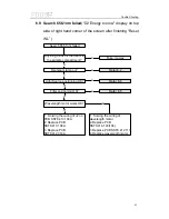
Страница 69: ...Trouble Shooting 64 6 8 Slit check failed Only for UV 2802S UV 2802PCS...
Страница 72: ...Trouble Shooting 67 6 13 Get dark current for a long time...
Страница 74: ...Trouble Shooting 69 6 15 Backlight OK but display nothing on LCD Display...
Страница 77: ...Trouble Shooting 72 6 18 No DC 12V on PCB SST8 412 113...


