


35
36
UT207A/208A/209A Operating Manual
UT207A/208A/209A Operating Manual
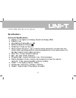
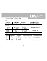
Specifications
A.General Specifications:
● Display: 3 3/4 digits LCD display, Maximum display 3999.
● Polarity: Auto
● Overloading: Display
OL
or
–OL
.
● Battery Deficiency: Display .
● Sampling: 3 times per second.
● Measurement Deviation: The conductor being meaured is not placed in the
center of the jaw during AC/DC current measurement, it will cause extra ±1%
deviation based on the stated accuracy.
● Drop Test: 1 meter drop test passed.
● Max. Jaw Size: 55mm diameter.
● Projected Max. Current conductor size: 45mm diameter.
● Electro-Magnetic: When carrying out measurement near the electro-
magnetic, it may cause unstable or wrong reading.
● Power: 1 x 9V battery (6LF22 1604A)
● Dimensions: 285.3mm x 105mm x 44.5mm
● Weight: Approximate 533g (battery included)
Содержание UT208A
Страница 1: ......
Страница 17: ...16 UT207A 208A 209A Operating Manual Measurement Operation A DC AC Voltage Measurement see figure 3 Figure 3...
Страница 25: ...24 UT207A 208A 209A Operating Manual Figure 6...
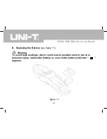
Страница 27: ...26 UT207A 208A 209A Operating Manual Figure 7...
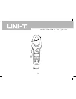
Страница 29: ...28 UT207A 208A 209A Operating Manual Figure 8...
Страница 33: ...32 UT207A 208A 209A Operating Manual Figure 9...
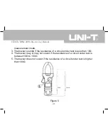
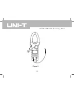
Страница 35: ...34 UT207A 208A 209A Operating Manual Figure 10...
Страница 47: ...UT207A 208A 209A Operating Manual...


