background image


SK00-9663-E8-003-00 


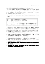
Control input/output signal 


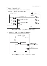
Photocoupler ratings [30V

MAX

, 50mA

MAX

, 70mW]


Fig. 3-1 SW100 output signal internal circuit diagram 


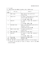
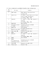
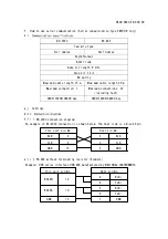
Control input signal (Analog output type SW100-A only) 


Fig. 3-2 SW100-A input signal internal circuit diagram 


+5V

+24V

 A

1

2

 A

1

2

 A

1

2

2:ERROR signal ON/OFF

3:SETPOINT signal-1 ON/OFF

15:GND

11:SETPOINT signal-2 ON/OFF

Internal circuit

PLC or PC

Internal circuit


Power supply


+5 V  

5:ADJUST input


15: GND


Internal circuit


Содержание G-Tran Series

Страница 1: ...eries Pirani Vacuum Gauge Sensor Unit Analog Output Type Model SW100 A Serial Communication Type Model SW100 R Specification ULVAC Inc Components Division 253 8543 2500 Hagisono Chigasaki Kanagawa Jap...

Страница 2: ...For details refer to the SW100 instruction manual USB Type C can be connected to a Windows Android device with UL MOBI installed using the USB cable and can be monitored and set by UL MOBI UL MOBI fo...

Страница 3: ...input signal Zero point atmospheric pressure adjustment adjustment reset Operates with open collector input negative logic Control output signal Sensor error signal setpoint1 2 Open collector output...

Страница 4: ...eating temperature Sensor only 150 without SW100 When heating deviations from specifications such as accuracy is observed The operating temperature range of SW100 is 10 to 40 Mounting position Free IP...

Страница 5: ...nforms to British legislation equivalent to EU Directives for CE standards listed above I O connector D sub15pin connector male M2 6mm screw USB Type C USB Type C can only be used for communication us...

Страница 6: ...unwired Calibration certificate Calibration certificate JCSS calibration certificate Inspection certificate Traceability certificate Display unit Model ISG1 DC24V power supply Display cable Between SW...

Страница 7: ...00 for both new installation and replacement and set and connect When used as a compatible unit the performance of SW100 A may be limited so please read the instruction manual UL MOBI can be downloade...

Страница 8: ...MAX 70mW 5 Adjustment input Input a signal when adjusting zero point or atmospheric pressure Operates when short with GND 8 Measure signal output It outputs a measured value DC 0V to 10V 9 Power suppl...

Страница 9: ...70mW 4 RS232C RxD RxD of RS 232C 5 Terminating resistor for RS485 Terminating resistor for RS 485 Connect with pin13 6 RS232C TxD TxD of RS 232C 8 Measured value output It outputs a measured value DC...

Страница 10: ...ted as OUTPUT see Section 1 4 of this manual follow the respective conversion formulas instead of the pressure conversion formulas in this section For details refer to the SW100 instruction manual Mea...

Страница 11: ...rcuit diagram Control input signal Analog output type SW100 A only Fig 3 2 SW100 A input signal internal circuit diagram 5V 24V A 1 2 A 1 2 A 1 2 2 ERROR signal ON OFF 3 SETPOINT signal 1 ON OFF 15 GN...

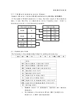
Страница 12: ...connection 1 Maximum connections 32 including host 9600 19200 38400 bps 9600 19200 38400 bps Settings RS 232C connection diagram An example of RS 232C connection is shown below The host side is a D s...

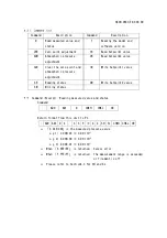
Страница 13: ...0 AD1 CMD D0 Dn SH SL CHKH CHKL CR Colon AD0 Device address higher 4bit 0 9 AD1 Device address lower 4bit 0 9 CMD Commands upper lower case sensitive D0 Data 4bit 0 9 A F Dn Data 4bit 0 9 A F SH Highe...

Страница 14: ...te Setpoint1 value SR Reading status 2W Write Setpoint2 value SW Writing status Command Excerpt Reading measured value and status Command AD0 AD1 D CHKH CHKL CR Return format from this unit to PC AD0...

Страница 15: ...is damaged due to problem during transportation at the time of delivery The warranty scope specified in the latest INCOTERMS shall be applied 3 A product that does not meet the basic specifications o...

Страница 16: ...party s claim that we infringe a patent 8 Sensor unit in use Lifespan due to the use measurement error due to contamination 9 Sensor cable in use Cable disconnection or poor contact due to improper in...

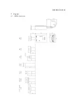
Страница 17: ...SK00 9663 E8 003 00 Diagrams...

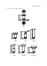
Страница 18: ...3 00 SWP Sensor for SW100 dimensions 46 40 30 SWP 16 NW16 66 60 47 41 40 77 83 18 SWP 25 NW25 SWP R1 8 R1 8 SWP P18 18tube 45 51 50 4 65 15 59 65 59 33 8 SWP P15 15tube SWP CF16 CF16 ICF034 SWP 1S ASM...

Отзывы: