background image

8

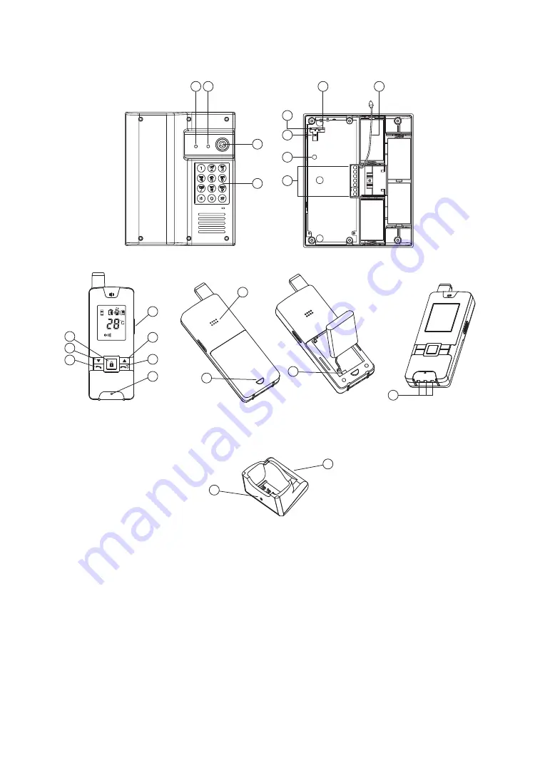
1. 

Call button

2. 

Door code entry keypad

3. 

Low battery indicator

4. 

Call indicator

5. 

Front or backgate selector

6. 

Internal or external antenna selector

7. 

Power supply selector

8. 

Pairing button

9. 

Terminal block

10.  External antenna cable
11.  Answer button
12.  Hang up and power ON/OFF button

13.  Door lock open button
14.  Press-to-talk (PTT) button
15.  Microphone
16.  Volume up button
17.  Volume down button
18.  Battery door lock button
19.  Speaker
20.  Li battery socket
21.  Charging contacts
22.   Charging indicator
23.   DC jack

Controls Layout

22

23

Handset

Charging Stand

19

18

13

14

16

12

15

17

11

20

21

3 4

6

10

1

5

7

8

9

2

Содержание UltraCOM2

Страница 1: ...INSTRUCTION MANUAL DOORPHONE WIRELESS UltraCom 600 600AK...

Страница 2: ...rference free conversation Two way communication Long operating range of 800m in open space Selectable audio visual or vibration alert for doorbell Indication of indoor temperature Remote control of e...

Страница 3: ...artment observe correct polarity 2 Alternatively the caller unit can operate with 12V DC supply if such supply is available at the entrance Connect the DC supply to the terminals 9 at the back marked...

Страница 4: ...ndset To replace battery press down the lock button 18 and slide open the battery door take out the battery and disconnect from to socket 20 TO AC OUTLET 23 22 Handset 4 The charging indicator 22 shou...

Страница 5: ...er unit has entered pairing mode Perform same for the caller unit that is intended to be used in backgate the switch 5 is set to position B 4 Now release both pairing button 8 and Call button 1 Press...

Страница 6: ...upply you prefer Remember to use only ONE type of power supply or otherwise the unit will not function normally In case 12V DC is selected connect to the terminals marked at the back of caller unit N...

Страница 7: ...minals act like a switch and will be short circuited for around 2 sec once the call button 1 is pressed However there is no voltage supply from the terminals They can be used to trigger a conventional...

Страница 8: ...lock 10 External antenna cable 11 Answer button 12 Hang up and power ON OFF button 13 Door lock open button 14 Press to talk PTT button 15 Microphone 16 Volume up button 17 Volume down button 18 Batte...

Страница 9: ...hime and vibrating alert selected Flashing light and vibrating alert selected Door chime flashing light and vibrating alert selected Door lock opened Caller unit battery low F Frontgate B Backgate Sel...

Страница 10: ...eaker volume icon Q will change correspondingly Please note the loudness of door chime is fixed and cannot be adjusted 7 Make sure there is power supply to the caller unit either by 12V DC or alkaline...

Страница 11: ...nction only available if your door is equipped with an electric latch Press the button 13 shortly wait for 4 5 seconds and the icon M appears on the screen showing the door latch is opened The icon M...

Страница 12: ...ble Intercom This function is applicable only if you have two or more handsets Please note all units must be paired together a Under standby mode momentarily press Answer button 11 a do do sound will...

Страница 13: ...ress of the Hang up button 12 to switch off handset then press again same button to switch it on and resume normal operation f To open door lock at gate press followed by the four digit code two Di Di...

Страница 14: ...ated Wrong connection at terminal block Activate door lock opening button 13 Make proper connection Cannot perform intercom between Handsets The unit are not properly paired Battery has run down Perfo...

Отзывы: