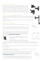
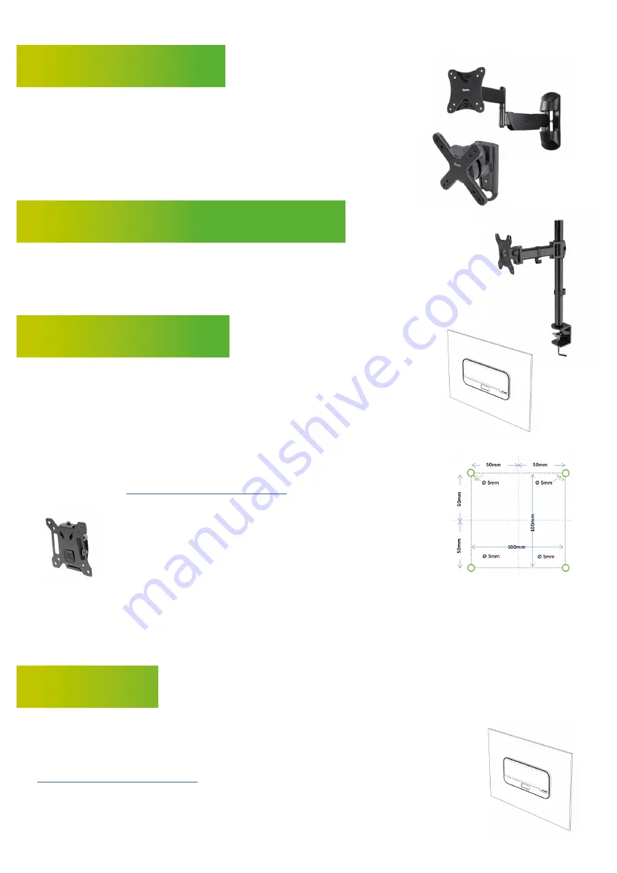
Using a standard TV or monitor mount, you can fix the STRATOS™ Inspire to a
solid or hollow wall. Any mount that is compatible with the VESA 100 standard
can be used for this purpose, although a version with tilt adjustment and/or an
adjustable arm position may be preferable to give flexibility of haptic positioning.
Once the desired position of the STRATOS™ Inspire has been established, wall
VESA mounts are first fitted to a wall using suitable fixings, generally supplied with
the mount. The STRATOS™ Inspire is then fitted to the mount using the VESA 100
mount.
VESA mounts that incorporate a clamp to fit a vertical monitor stand pole or a desktop are also
available. These mounts often incorporate tilt and position adjustment, providing a high degree
of flexibility.
These mounts are first clamped to the pole or desk, then the STRATOS™ Inspire is fitted using
the VESA 100 mount bolts.
STRATOS™ Inspire can be screwed directly onto a plinth, cabinet front or hollow
wall.
To do so, first establish the desired position of the haptic interaction zone. Should
a tilt be required, for example to project haptics in front of a display mounted
above the array, this should be accounted for in the design of the cabinet or plinth
in use.
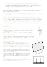
Next, mark and drill 4 holes in the mounting surface spaced as shown at right. A
template is provided with the product for this purpose; for automated cutters or
CAD, Ultrahaptics provides .dxf and .pdf files of the required hole positions on
our developer site,
https://developer.ultrahaptics.com
, as well as a .STEP file of
the complete product
If preferred, this operation may be replaced by the use of a
generic ‘flat-to-wall’ VESA 100 compatible mount, such as
that shown at left.
A 5th hole will be required to enable the power and USB
cables to pass through the wall. This should be positioned
below the USB and power cords. A suggested position is shown in the template shipped with the product,
and in the CAD available from Ultrahaptics. A minimum hole size of 25mm / 1” is recommended to simplify
connection.
A 6th hole (shown in CAD and mounting template) may be required should a security leash be used with the
security bolting point (9).
STRATOS™ Inspire is designed to fit part-recessed into a cabinet, hollow wall or plinth. This provides a
minimalist appearance, similar to a speaker grille.
A hole is required to be cut into the outer surface to facilitate this. A cutter guide is provided
on the installation template shipped with the product. For automated cutters or CAD,
Ultrahaptics provides .dxf and .pdf files of the required hole positions on our developer site,
https://developer.ultrahaptics.com
, as well as a .STEP file of the complete product.
Once the hole has been formed, the body of the STRATOS™ Inspire is mounted inside the
unit, with the lip of the mounting hole resting against the flange around the front of the
array. A silicon or foam seal may be used behind the flange to provide protection for the


