background image

ten lageunabhängig und enthalten eine Arre-
tierungsvorrichtung,  mit  der  die  Bandspulen
gegen  ein  Herabfallen  gesichert  sind.  Die
Bremsung  der  Kupplungsoberteile  erfolgt
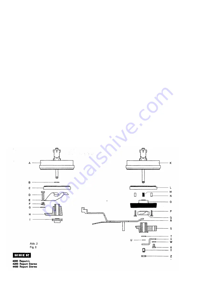
über  die  Klemmrollen  (O),  die  in  angedrück-
tem Zustand zwischen das Kupplungsoberteil
und  die  Zunge  (P)  geklemmt  werden.  Das
Antriebsrad  (Q)  treibt  über  den  Riemen  (R)
das Zählwerk (S) an.

weight  of  the  applied  real.  Therefore,  the
clutch action is constant over almost the entire
lenght  of  the  tape.  The  clutches  will  operate
regardlese 

of 

position. 

Each 

turntable

comprises  a  locking  sleeve  which  secures  the
respektive  tape  reel  against  coming  off  the
spindle.  The  turntable  drums  are  braked  by
means  of  braking  rollers  (O)  which,  when
applied,  are  squeezed  between  the  respektive
turntable  drum  and  the  strip  (P).  The  pulley  Q
drives  the  digital  Counter  (S)  via  the  driving
belt (R).

bände 

sur 

toute 

sa 

longueur. 

Les

embrayages 

travaillent 

de 

mäme

parfaitement  dans  uns  position  quelconque.
Ils  comportent  un  dispositif  de  retenue  qui
ävite  toute  chute  accidentelle  des  bobines.
Le galet (O) insärä entre la languette (P) et la
partie  supärieure  d'embrayage  assure  le
freinage  de  kette  derniäre.  La  roue  (Q)
entraine  la  compteur  (S)  par  I'intermädiaire
de la courroie (R).

1.2 Das Prinzip des Motors
Der  Motor  besteht  aus  einem  rotierenden
Permanentmagneten,  den  feststehenden  An-
kerwicklungen  und  einem  feststehenden  zy-
lindrischen Eisenkörper, der die ganze Einheit
umkleidet.  Die  Ankerwicklungen  werden  über
eine 

mehrstufige 

Transistorschaltung

gespeist.
Ein  Anlaufverteiler  steuert  die  Transistor-
schaltung  in  Abhänigkeit  von  der  Rotorstel-
lung.  Durch  Fliehkraft-Einwirkung  wird  die
Steuerung  über  den  Anlaufverteiler  lange  vor
Erreichen  der  Solldrehzahl  unterbrochen.
Nach  Erreichen  der  Solldrehzahl  verwendet
man  die,  durch  den  Permanentmagnet-Rotor
in  den  Ankerwicklungen  erzeugten,  Wechsel-
spannungen  zur  Steuerung  der  Transistor-
Schaltung.
Durch  Gleichrichtung  der  Wechselspannun-
gen  wird  die  nötige  Information  zur  elektro-
nischen Drehzahlregelung gewonnen.

1.2 Concept of the Motor
The  motor  consists  of  a  rotating  permanent
magnet,  stationary  armature  windings  and  a
stationary  cylindrical  iron  body,  which  em-
braces  the  entire  unit.  The  armature  windings
are  fed  through  a  multi-stage  transistor
network.
A  starting  distributor  controls  the  transistor
network in accordance with the position of the
rotor.  The  control  link  via  the  starting
distributor is disconnected by centrifugal force
long before the motor reaches its rated speed.
After  the  rated  speed  has  been  reached,  the
AC-signals  induced  in  the  armature  windings
by  the  permanent  magnet  of  the  rotor,  are
used for controliing the transistor network.
The  Information  for  the  electronic  speed  con-
trol  is  obtained  by  rectification  of  the  AC-
signals.

1.2 Principe du moteur
Le moteur se compose d'un aimant permanent
tournant,  d'enroulements  d'induit  fixes  et  d'un
Corps  de  fer  cylindrique  fixe  qui  entoure
I'ensembie.  Les  enroulements  de  I'induit  sont
alimentäs ä travers un montags de transistors
ä plusieurs ätages.
Un  distributeur  de  dämarrage  commande  le
montage  de  transistors  en  däpendance  de  la
position  du  rotor.  Gräce  ä  un  effet  de  Force
centrifuge, son action sur la montage de tran-
sistors  kesse  bien  avant  que  le  moteur  Wat-
teigne sa vitesse nominale.
Lorsque  la  moteur  tourne  ä 

sa  vitesse  no-

minale,  las  tensions  alternatives  gänäräes
dans las enroulements 

de l'induit par le rotor

ä  aimant  permanent,  servent  ä  la  commande
du montage de transistors.
Par  redressement  des  tensions  alternatives,
an  obtient  I'information  näcesseire  ä  la  rä-
gulation älectronique de la vitesse du moteur.

1.3 Verstärker

1.3 Amplifier

1.3 Amplfficateur

1.31 Verstärker für Typ 4000 Report-L

Der  kombinierte,  transistorisierte  Aufnahme-
Wiedergabeverstärker  ist  vierstufig.  Er  ist  in
gedruckter Schaltung ausgeführt und

1.31 Amplifier for the model 4000 Report L

The  transistorized  combination  record

i

ng/

playback  amplifier  has  four  stages.lts  printed-
circuit board can be hinged out. The push

1.31 Amplificateur pour le modäl

4000 Report L

L'amplificateurtransistorisä d'enregistrement/
lecture a quatre ätages. 11 est exäcutä sous

Содержание 4000 REPORT-L

Страница 1: ...Service...

Страница 2: ...Contact pour la regulation de la vitesse du moteur 14 4 2 Contact muet 14 4 3 Interrupteur et selecteurde vitesses 15 4 4 Commutateur de piles 15 4 5 Interrupteur separateur 4 8 Commutateur de correct...

Страница 3: ...the shaft I are driven via the belt F Each friction wheel is fitted with a conically ground rubber lining For better understanding of the functioning of the clutch K it seems necessary to explain its...

Страница 4: ...n zur elektro nischen Drehzahlregelung gewonnen 1 2 Concept of the Motor The motor consists of a rotating permanent magnet stationary armature windings and a stationary cylindrical iron body which em...

Страница 5: ...the power sources 1 32 Amplificateur pour les models 4200 4400 Report Stereo L amplificateur st reophonique d enregistre ment lecture est transistorise et comporte quatre etages pour chaque canal il...

Страница 6: ...the start key and depress the fast forward key Upon this there must not be any frictional engagement left between the driving disk A and the tone of the friction wheel B There must be a clearance of...

Страница 7: ...ou encrass e Nettoyer ensuite la surface de roulement des parties sup rieures d embray ages Une possibilit d ajustage n est pss n cessaire et n est pss pr vue pour la friction entre le plateau d acco...

Страница 8: ...lge eingehalten wird Zuerst mu die Bremsrolle vom Kupplungs oberteil abheben und anschlie end die An druckrolle das Band gegen die Tonwelle dr cken 222 Adjustment see Fig 6 In the Stop position the br...

Страница 9: ...Sechskantschrauben C und D Verschieben nach links vermindert nach rechts erh ht den Andruck 2 32 Adjustment see Fig 7 The adjustment made at the factory should not be changed unless the desired value...

Страница 10: ...l commande La relais Stop dolt tre attir et bloquer la transport de la bande 2 42 Einstellen siehe Abb 7 Gegebenenfalls ist das Gest nge zum Stop relais zu justieren Dazu wird bei eingelegtem und gest...

Страница 11: ...provoque I arr8t de la roue friction respektive 2 54 Einstellen des Vor und R cklaufes siehe Abb 8 und 9 Die Einstellung erfolgt durch Biegen der Fe der H f r Vorlauf bzw der Feder I f r R cklauf mitt...

Страница 12: ...derni re a ete d reglee ou echangee apres son montage la t te magnetique doit tre demagn tisee 2 71 Pr fen der H henverstellung Die Stirnfl che des Tonkopfes mu parallel im Tonband stehen Die verschie...

Страница 13: ...r une couche de vernis 2 8 Geschwindigkeitsw hler Auf unbedingte Sauberkeit der Gummilauf fl chen des Antriebsrades sowie der Lauf fl che von Motorrolle Antriebsriemen und Schwungmasse ist zu achten B...

Страница 14: ...and the fast forward rewind seesaw 2 91 Echange du moteur voir fig 12 Retirer fas vis A et B debrancher las fils de raccordement du moteur C et sortir ce dernier Remonter le nouveau moteur de teile fa...

Страница 15: ...points must be lubricated with a non gumming multi purpose grease after approximately 500 hours of operation in any event avoid a too generous use of lubricants since surplus grease or oil may reach...

Страница 16: ...ew A and pivot the mounting angle B Then tighten the screw Q 4 12 R glage voir fig 13 Le reglage s op re apres le desserrage de la vis A par le deplacement de I querre de retenue B Resserrer ensuite l...

Страница 17: ...4400 Report Stereo Le contact K9 K5 est actionne lors de lamise en piace de I accumulateur ou du bloc sec teur chargeur dans le casier des piles 4 41 Pr fen Der Kontakt K 9 bzw K 5 mu bei eingeleg te...

Страница 18: ...erneath the contact springs When the contact is open the clearance between the contact points must be approximately 0 1 mm 0 004 4 62 Reglage Le contact rei a doit demeurer ferm lors que son relais n...

Страница 19: ...ors respecter las prescriptions eta blies par les constructeurs de transistors 5 1 Elektrische Einstellungen und Me werte Das beiliegende Schaltbild enth lt auf seiner R ckseite die entsprechenden Reg...

Страница 20: ...cps 1 000 cps 1 250 cps 1 600 cps 2 000 cps 2 500 cps 3 150 cps 4 000 cps 5 000 cps 6 300 cps 8 000 cps 10 000 cps 12 500 cps 18 000 cps 20 000 cps 1 000 cps en 19 05 cm s 1000 Hz 40 Hz 63 Hz 80 Hz 10...

Страница 21: ...cps and adjust the output voltage of the audio oscillator in such a manner that the connected VTVM reads apprpximately 1 0 volt Thereafter do not vary the Output voltage of the oscillator any more 5 4...

Страница 22: ...e is recom mended Thread a UHER Test Tape turn the recording level control to its extreme anticlockwise position and erase both tracks Connect an audio frequency millivoltmeter across the contacts 3 a...

Отзывы: