background image

18

MT GL/GLS/UL

polycarbonate.

13. 2 REFRIGERANT CIRCUIT SERVICE 

13. 2. 1 CHECKING FOR REFRIGERANT LEAKS

The following procedure is the recommended approach to
systematically inspect the entire system for refrigerant leaks.

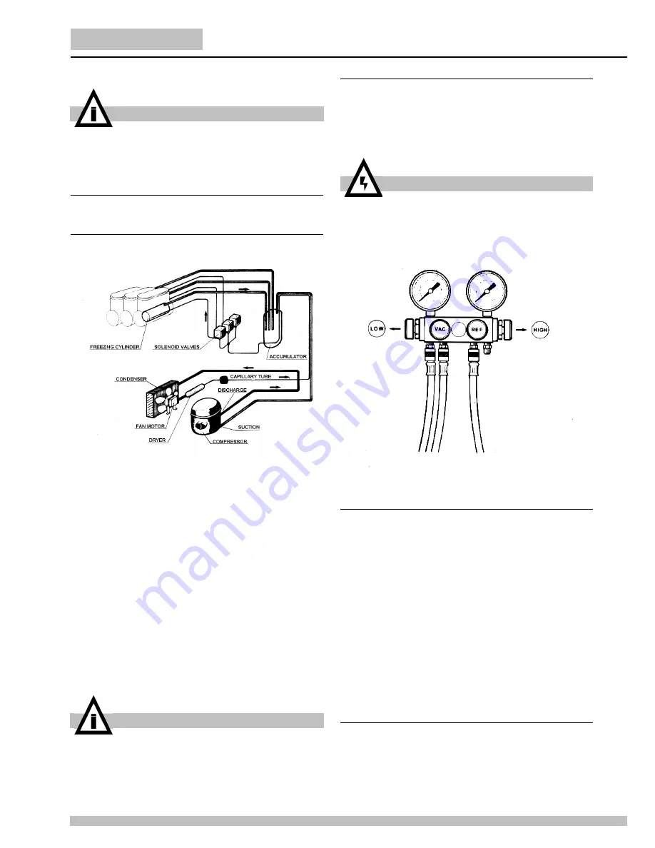
figure 13

NOTE

: when using refrigerant leak detector, follow along the

bottom side of the copper tubing. The refrigerant gas is heavier
than air. Where copper tubing is protected by an insulating
jacket, check for leaks at both ends of each jacket section.
Referring to figure 4, perform the following steps:

1

Start inspection at the high pressure line of the compressor.

Check around the soldered connection. 

2

Follow the copper tubing to the condenser and check

around the soldered connections at the top and bottom of the
condenser.

3

Check also along the copper curves on both sides of

condenser.

4

Follow the copper tubing to the evaporators, checking

around the soldered connections of dryer and solenoid valves.

5

Remove mixer motors and check the inlet (capillary) and

outlet (suction) tubing.

6

Check the copper tubing all the way back to the

compressor.

7

Check around the low side connections of the compressor

suction and process tubes.

If a leak has been detected, seal it and make a new refrigerant
charge as per instructions in the following paragraphs.

13. 2. 2 DISCHARGING

1

Remove the dispenser panels.

2

Remove the screw cap from the compressor process tube. 

3

Connect the process tube to the LOW part of the gauge set.

4

Connect the VAC port of the gauge set to an adequate

approved gas recovery system.

5

Open the LOW and VAC valves and recover the refrigerant. 

6

Once the recovery operation is completed, close the LOW

and VAC valves and disconnect the recovery system.

figure 14

13. 2. 3 EVACUATING

Always install a brand new liquid line filter dryer before
evacuating.

1

Connect the REF port of the gauge set to the charging unit. 

2

Connect the VAC port of the gauge set to the vacuum pump

and open the VAC valve.

3

Open the line valve of the charging unit and, for a while,

also the REF valve so as to purge air from the REF hose.

4

In multiple bowl models, disconnect the dispenser internal

wiring from all solenoid valves and energize them directly
through an external power source. This way the valves are
opened and the entire system is ready to be evacuated. 

5

Open the LOW valve of the gauge set and turn on the

vacuum pump for a minimum of half an hour.

6

While the pump is running, close the VAC valve once a

vacuum has been established.

7

Turn off the vacuum pump. 

8

Disconnect the solenoid valves from the external power

source and restore the internal wiring.

13. 2. 4 CHARGING

In the figure 4, the gauge set is shown with four ports (and four
valves) which is the easiest option to be found in the market
since it allows the charging through both low and high side of the
system. Our refrigeration systems are manufactured so as to be
chargeable through the compressor process tube only (low
side): thus, the HI port is never mentioned nor used in the

IMPORTANT

The electric diagram of the dispenser is located in the
inner part of the dispensing side panel.

IMPORTANT

To check for a leak in the low side of the system, it is
advisable to have the evaporators at least at ambient
temperature.

ATTENTION

The refrigerant gas could be highly acid and toxic.

Содержание MT GL

Страница 1: ...MANUALE DI SERVIZIO SERVICE MANUAL MT GL GLS UL...

Страница 2: ...2 MT GL GLS UL...

Страница 3: ...ts Cet appareil est couvert par un ou plusieurs des brevets suivants et ou autres demandes de brevet d pos es Dieses Ger t ist durch eines oder mehrere der folgenden Patente und oder andere eingetrage...

Страница 4: ...uendo quanto previsto nel libretto di istruzioni capitolo 5 3 PULIZIA fornito con il distributore stesso 9 Qualora il distributore venisse trasportato in modo impro prio coricato su di un lato o roves...

Страница 5: ...particolare in prossimit dei pannelli grigliati Assi curarsi inoltre che il flusso d aria non venga ostacolato dalla vicinanza di pareti scatole o altro Lasciare almeno 15 cm di spazio libero intorno...

Страница 6: ...nziona come un Refrigeratore di bevande indipendente dagli altri contenitori In queste condizioni il raffreddamento della bevanda all interno del contenitore controllato da un termostato uno indipende...

Страница 7: ...circa 2 minuti dopo l accensione della macchina 4 La partenza del compressore circa 2 minuti dal momento in cui il microinterruttore modo Granita o termostato modo Bibita vengono attivati 5 Solo sui m...

Страница 8: ...ercafughe indirizzare sempre il senso re verso la parte inferiore dei tubi di rame Il gas refrigerante pi pesante dell aria Dove il tubo di rame protetto da un manicotto di isolante la ri cerca della...

Страница 9: ...re la spina della macchina ad una presa di corrente e mettere l interruttore generale in posizione I 4 Mettere tutti gli interruttori Mescolatori e Refrigerazione in posizione I ed attendere che tutte...

Страница 10: ...l Pro tettore termico Controllare il voltaggio della presa di corrente Controllare la viscosit del prodotto Controllare la ventilazione del condensatore alette ostruite o motoventilatore non funzionan...

Страница 11: ...o correttamente Microinterruttore densit danneggiato Sostituire microinterruttore Poco gas nel circuito frigorifero Verificare l eventuale presenza di una fuga di gas Una volta trovata sigillare il pu...

Страница 12: ...12 MT GL GLS UL 7 SCHEMI ELETTRICI PER MACCHINE PRODOTTE FINO A MARZO 2002 7 1 VERSIONE GLS 7 2 VERSIONE GL UL...

Страница 13: ...13 8 SCHEMI ELETTRICI PER MACCHINE PRODOTTE DOPO APRILE 2002 8 1 VERSIONE GLS 8 2 VERSIONE GL UL...

Страница 14: ...nitized from the factory Before serving products the dispenser must be disassembled cleaned and sanitized according to Operator s Manual chapter 5 3 CLEANING AND SANITAZING PROCEDURES 11 OPERATIONAL T...

Страница 15: ...r cap when the unit is used in Soft Drink mode it is advisable to install the restrictor cap on the faucet outlet in order to reduce the drink outflow vedere figure 5 figure 9 11 2 MIX PREPARATION 1 T...

Страница 16: ...the unit once taken away the rear cover 12 3 PRINTED WIRING BOARD PWB CONTROL MACHINES MANUFACTURED UNTIL DECEMBER 2001 The device is designed to delay 1 The opening energizing of solenoid valves 10 1...

Страница 17: ...tions In case the warning light is still ON even after these operations have been carried out it will be necessary to remove the dispenser panels and inspect if the fan motor is working 13 ROUTINE MAI...

Страница 18: ...LOW and VAC valves and recover the refrigerant 6 Once the recovery operation is completed close the LOW and VAC valves and disconnect the recovery system figure 14 13 2 3 EVACUATING Always install a...

Страница 19: ...d discharge pressures of the machines with the different refrigerants They must be verified under the following conditions Ambient temperature 32 C Product temperature in the bowls 0 C Evaporation tem...

Страница 20: ...al pro tector Check for proper line voltage Check for proper product viscosity Check for proper condenser air flow obstructions or inoperative fan motor Burned out or discontinued stator win ding Repl...

Страница 21: ...oswitch Replace microswitch Poor refrigerant charge Detect possible leak seal it and make new refrigerant charge PWB malfunction only for unit manufactured before january 2002 Replace PWB Solenoid val...

Страница 22: ...22 MT GL GLS UL 15 WIRING DIAGRAMS MACHINES MANUFACTURED UNTIL DECEMBER 2001 15 1 GLS VERSION 15 2 GL UL VERSION...

Страница 23: ...23 16 WIRING DIAGRAMS MACHINES MANUFACTURED AFTER JANUARY 2002 16 1 GLS VERSION 16 2 GL UL...

Страница 24: ...Ugolini spa Via dei Pioppi 33 20090 Opera MI Tel 02 530059 1 Fax 02 530059260 www ugolinispa com E Mail sales ugolinispa com 2429_29 R2 4 06G19...

Отзывы: