background image

38

Appendix B: Soil Property Field Test

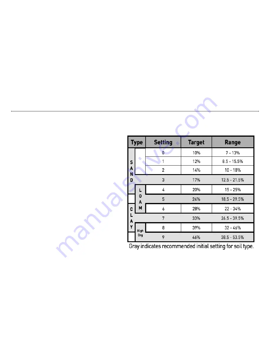
It is very important to determine the type of soil the sensors are being placed into in order to set an initial moisture setting on the base station.  
While there are 12 types of soil with endless variations found in the field, we can narrow this to 4 types for installation purposes:

Type 1: Sand with an initial UgMO setting of 3

Type 2: Silty Loam with an initial UgMO setting of 5

Type 3: Clay with an initial UgMO setting of 7

Type 4: Highly Organic with an initial UgMO setting of 9

Содержание ProHome PH100WS

Страница 1: ...Installation and User Manual UgMO Technologies 840 First Suite 300 King of Prussia PA 19406 www UgMO com Please leave with property owner ...

Страница 2: ...Installation and User Manual ...

Страница 3: ...test or driest conditions expected UgMO limits watering to be just enough UgMO wireless sensors have a patented electronic moisture sensing circuit and low power radio signal Two uniquely configured batteries supplied and installed provide an operating life of up to 5 years The UgMO Base Station is powered by your Irrigation controller Installation requires only basic electrical tools a wire strip...

Страница 4: ...ions with a Pump Master Valve to Control Up to 12 Stations 11 Base Station User Interface 14 Main Screen 14 Auto Bypass Indicator 15 Pump Master Valve Indicator 15 Water Savings Indicator 15 Zone Control Indicator 15 Zone Moisture Level Indicator 16 Battery and Wireless Strength Indicator 17 Set Contrast 17 Manage Sensors 18 Pairing sensors to Base Station Choosing Sensors 18 Assigning a Common Se...

Страница 5: ...ure Override 24 Manage Zone Settings 25 Zone Bypass Setting 25 Multiple Sensors Per Zone Settings 26 View Sensors 27 Determining Wireless Signal Strength 27 Reading the View Sensor Screen 28 Activating the Archives 29 Installing Sensors 30 Placement of Sensors 32 Completing the Installation 34 Appendix A Troubleshooting Guide 36 Appendix B Soil Property Field Test 38 Appendix C Watering Guidelines...

Страница 6: ... connections 8 Wiring Harness 18 conductor cable and strain relief leading to irrigation clock 9 Selection wheel 10 Lit when UgMO is allowing watering and zone valve is open 11 Check valve light illuminates when UgMO identifies a wir ing short in existing irrigation system 12 Zone numbers corresponding to LCD screen UgMO Wireless Sensor 13 Tine Sensor element that measures moisture level and tempe...

Страница 7: ...3 13 14 15 ...

Страница 8: ...o test AC polarity and confirm proper wiring Screwdriver Phillips 1 2 and small electrical screwdrivers for tightening terminals Cordless Drill Bits For drilling holes for mounting screws One Inch 1 Hole Saw Bit For drilling a hole into the irrigation clock Wire Strippers Side Cutters and Crimpers Necessary to install Base Station Shovel or Hole Cutter For digging holes for placement of sensors 1 ...

Страница 9: ...in an area that tends to be the driest and where you have the best line of sight to the Base Station with the least obstructions Generally high spots are the dri est and low lying areas should be avoided Identify any operating issues with the clock valves and or sprinklers 3 Note different types of hardware Drip irrigation Rotor Heads Spray Heads 4 Note different types of zone plantings Turf Shrub...

Страница 10: ...ptimum location for the UgMO Base Station use the Base Station Bracket mounting plate as a template to mark the drilling locations 3 Drill two holes small pilot holes if mounting to a solid material like wood or larger holes to accommodate a drywall stucco or concrete alligator anchor Tapcon screws are also an option 4 Secure the mounting plate to the wall 5 Insert the Bracket Arm into the Bracket...

Страница 11: ...nly of inch in size 3 Remove the jam nut from the wire strain relief and carefully insert the 18 conduc tor wiring harness from the Base Station into the irrigation clock through the one inch hole Thread the wires from the wir ing harness through the wire strain relief nut inside the irrigation clock and insert and secure the male end of the wire strain relief by screwing the jam nut on 4 The wiri...

Страница 12: ...d the wire in step 7 above 9 Repeat steps 5 thru 8 above for all valve station wires using the labels on the wires to identify the proper station and valve wires Refer to the Wire Reference Guide to the right for the proper wire connections This guide is also provided as a convenient sticker for inside the irrigation clock for easy reference 10 If you identify that the irrigation clock has a Pump ...

Страница 13: ...entify the common wire s in the irrigation clock detach them from the terminal and butt connect them to the WHITE wire labeled COM OUT V from the Power Bundle and crimp them so they are attached securely Depending on the number of common wires present a wire nut may need to be used to twist all the wires together instead of a butt connector 14 Identify the TAN wire labeled COM IN C from the Power ...

Страница 14: ...l 8 Attach the RED wire from the base station wiring har ness to the AC terminal 9 That s it The wiring phase of installation is over Now it s time to check your work to be sure that you can control each valve 10 On a simple installation like this one you can simply turn on power then se quence the Irrigation Con troller to manually power each zone Confirm that each zone turns on and then turns of...

Страница 15: ...nd attached that wire in the irrigation clock s Valve Station 1 terminal where you removed the wire in step 3 above 5 Remove the wire in the irri gation clock from the Valve Station 2 terminal and butt connect it to the WHITE wire with a RED STRIPE labeled V2 V8 from the Valve Bundle and crimp it so it is attached securely IMPORTANT NOTE Determine if the irrigation system uses a pump or master val...

Страница 16: ... the proper station and valve wires Refer to Wire Reference Guide on page 8 8 Next hook up the Pump Relay and or Master Valve by connecting the wires from the Base Stations and Irrigation Clock in series 9 Identify the GRAY wire labeled PM V from the Valve Bundle coming from Base Station 1 and butt connect it to the BROWN wire labeled PM C from the Clock Bundle from Base Station 2 and crimp it so ...

Страница 17: ... irrigation clock labeled P MV or Pump Master where you removed the wire in step 10 above 12 Identify the common wires in the irrigation clock and detach them from the terminal Using a wire nut attach them securely to the WHITE wires from both base stations labeled COM OUT V Attach the TAN COM IN C wires from both base stations to the clock COM terminal 13 Finally connect the AC power according to...

Страница 18: ...up you ll see the Introduction Screen This times out after 10 seconds or press the Select Button 4 on page 2 to display the Main Screen 2 The Main Screen is divided into six main sections identified as A F on the figure to the right MAIN SCREEN ...

Страница 19: ...ating when a zone is turned on This area flashes ON whenever UgMO allows a zone to come on regardless of the presence of a Pump or Master Valve Water Savings Indicator Displays a calculation of the average time UgMO did not allow the irrigation clock to water In this example UgMO reduced the total watering time by 33 since the system was last restarted Zone Control Indicator There are six columns ...

Страница 20: ...d for this zone Indicates that the moisture level is above the programmed UgMO moisture levels and no watering will be allowed for this zone Indicates that the soil temperature is below the pro grammed temperature setting and no watering will be allowed for this zone When a zone flashes OFF this indicates that the irrigation clock is requesting water but UgMO is not allowing it When the zone flash...

Страница 21: ...ol indicates several missed signals from the sensor These indicate no wireless connection to the sensor This will appear briefly after a sensor has been paired to a zone until a signal is received If radio signals have been lost for 4 days or upon reset of the Base Station hold down Select for 3 4 seconds then release these symbols will appear Rotating the selection wheel while in the main screen ...

Страница 22: ...he figure to the left 4 Press Select The A will be highlighted and Add will appear 5 Press Select The following screen will appear 6 This screen allows you to choose your method of entry The Choose Sensor option will display all of the NWAs that are within range of the base station and allows you to choose the one you want This is the recommended method Manual Entry allows a network address NWA to...

Страница 23: ...ollowing menu choices have appeared and you can navigate to them with the Selection Wheel S Save C Clear B Back 11 With the NWA highlighted press Select The first Zone position is reserved for assigning a Common Sensor See Assigning Common Sensor on next page You can scroll through the zone positions 1 6 to choose the zone to assign the sensor to The figure to the left shows the sensor assigned as...

Страница 24: ...the common sensor data is ignored COMMON POSITION ZONE POSITION 1 Only one sensor can be assigned as a common sensor at a time 2 Choose a sensor that is nearest to the base station with a strong wireless signal and a zone that is drier than average 3 When pairing this sensor navigate to the common position nearest Zones Press Select and rotate the wheel until C is shown Press Select 4 Rotate the w...

Страница 25: ...igning more than one sensor to one zone It is also possible to assign more than one Sensor to a single zone That zone can be set to manage the zone to the WETEST sensor reading DRIEST sensor reading or the AVERAGE reading of all of the sensors assigned to that zone See Manage Zones settings Editing an assigned sensor Any assigned sensor including a common sensor can be edited by scrolling to Manag...

Страница 26: ...elect to enter the selection Rotate the Selection Wheel to enter any other non zero digits After entering the last digit the second zone position will be highlighted and you will be able to assign the sensor to the correct zone and or assign it as a common sensor BE SURE TO SAVE EACH SENSOR ASSIGNMENT UgMO allows you to manually pair sensors to a base station This is particularly helpful if a sens...

Страница 27: ... can now choose additional zones to set or rotate to X to exit the screen Setting Global Auto and Bypass 1 When the system is set to Auto UgMO controls the zone watering When set to Bypass in this screen UgMO will not control ANY zones This setting is useful when testing the irrigation clock in manual mode From the Main Screen turn the scroll wheel up one click to the Man age System Settings page ...

Страница 28: ...in the middle of the screen is highlighted 4 Press Select and scroll to change the temperature to the desired level 5 Press Select and scroll to the X on the right side of the screen 6 Press Select and scroll to Exit Menu and press Select to return to the main screen Setting Global Cold Temperature Override The Cold Temperature Override is set globally and will not allow watering when the soil tem...

Страница 29: ...e Zone Settings page 1 Rotate the Selection Wheel until Manage Zone Settings is displayed 2 Press Select 3 The bubble next to Sensor is filled to indicate the zone is managed by the sensor s 4 Rotate to Bypass and press Select 5 Selecting Always OFF will set the system so even if the irrigation clock requests water the zone will not turn on 6 Scroll to X to exit this screen 7 Press Select and scro...

Страница 30: ...reading or the Wettest sensor reading 1 Rotate the Selection Wheel until Manage Zone Settings is displayed 2 Press Select 3 The bubble next to Average is filled to indicate the zone will average the wetness data of all sensors assigned to the zone 4 Scroll to highlight either Wettest or Driest to change this selection 5 Press Select to enter this setting 6 Scroll to X to exit this screen 7 Press S...

Страница 31: ...nal quality temperature and wetness level of an individual sensor Press Select until the desired sensor is displayed Be sure to match the NWA number if more than one sensor is assigned to a zone 3 To see other sensors make sure the arrow at the bottom right hand corner is highlighted and press Select to toggle through the rest of the sensors Determining Wireless Signal Strength ...

Страница 32: ...the last 60 min utes 100 means that 100 of the expected transmissions have been received 000 means that it has not received any transmis sions within the last 60 minutes Long Term Signal Qual ity Indicator This graphic represents the quality of the transmissions received from the sensor over the past four 4 days Each vertical column represents a 90 minute period If there are gaps or the columns va...

Страница 33: ...ould light up and the word Activating will appear in the middle of the screen this may take 15 to 30 seconds 5 The small bubble on the left side of the word Activate will now have a dot inside it indicat ing that it has been selected 6 Scroll to the X on the right side of the screen and press Select 7 Scroll to Exit Menu and press Select again to return to the main screen Activating the Archives T...

Страница 34: ...ressing and holding the select button down for 4 seconds and then releasing The Base Station will go dark and then come back on to the intro duction screen for about 10 seconds before presenting the main screen The main screen should show all of the zones with an XX at the bottom of the columns You should begin to see each sensor come on line and the XX icon go to a solid square and a full antenna...

Страница 35: ... IMPORTANT NOTE SENSOR NOT CONNECTING If any sensors are not communicating XX on the main screen is not being replaced by a full antenna after 12 minutes refer to the trouble shooting guide for solutions ...

Страница 36: ...ide of the sensor body not sensor blade away from the base station See figure on pre ceeding page This will allow for easy location of the sensor since you know which way it is orientated in relation to the Base Sta tion and whisker marker Do not be overly concerned about the height of the whisker marker it can be cut by the lawn mower without damage IMPORTANT NOTE RECORD LOCATION OF SENSOR Once a...

Страница 37: ... whisker making sure to pack the soil firmly as you fill the hole and place the turf cap back on 8 Repeat steps 6 9 for all sensors Repeat the field soil test only if you are dealing with different types of soils for the different zones flower beds turf areas mounds valleys etc 9 Once all sensors are buried return to the Base Station and restart it Wait to see if all the sensors can communicate to...

Страница 38: ... all zones are working you may have to set the UgMO Base Station to Bypass if soil conditions are wet because UgMO may not allow watering See page 15 On the front face of the Base Station the Watering Requested and Watering Al lowed LED s should light up with each zone Make sure sensor locations are recorded on the Sensor Location Reference Guide and guide is placed inside the clock Clean up entir...

Страница 39: ...35 Zone nWA reference 1 Measurement reference 2 Measurement 1 2 3 4 5 6 7 8 9 10 11 12 ugMO ProHome Sensor Location reference Guide ...

Страница 40: ... is a wiring issue 1 AC and AC wires are not attached correctly 2 Irrigation clock is not powered 1 Move sensor to a location closer to the Base Station 2 Orientate it to remove or limit obstructions from line of site Excavate power cycle by replacing tine sleeve and removing it and confirm above ground communication Rebury 1 If the zone reads WET on the Main Screen place Base Station into ByPass ...

Страница 41: ...ere is any voltage If yes the clock is still powering the zone If no go to the next solution 2 Inspect valve flow control setting 3 Inspect shape and condition of valve diaphragm If the lawn appears to be too dry check the UgMO screen to see the present moisture conditions If it reads DRY add additional watering time to that zone on the irrigation clock If it reads OK increase the moisture setting...

Страница 42: ... setting on the base station While there are 12 types of soil with endless variations found in the field we can narrow this to 4 types for installation purposes Type 1 Sand with an initial UgMO setting of 3 Type 2 Silty Loam with an initial UgMO setting of 5 Type 3 Clay with an initial UgMO setting of 7 Type 4 Highly Organic with an initial UgMO setting of 9 ...

Страница 43: ...ws using the soil tester illustrated below Step 1 Take a handful of soil from the depth where the sensor will be placed and fill the inside cup of the soil tester Be sure that the soil is firmly placed in the cup by pressing on it with your palm ...

Страница 44: ...rty Field Test Step 2 Saturate the soil with water slowly so that the water absorbs through the entire soil sample This takes about a minute for most soils It is important that the soil is saturated before continuing to step 3 ...

Страница 45: ...soil tester shut as firmly as possible to force soil and water to the holes at the bottom of the tool The reaction of the soil at the holes is what will determine the soil type for installation and threshold setting purposes ...

Страница 46: ... tool Use the scale to determine what soil type and setting should be used Type 1 Indicated by semi clear water exiting the holes Very few or no sand soil particles present Inital setting 3 Type 2 Indicated by moisture with soil sediment in it This sediment may come out in larger pieces but not formed like clay Initial setting 5 ...

Страница 47: ...Indicated by formed soil extensions exiting the holes Initial setting 7 Type 4 Indicated by very dark muck like water from organic deposits in soil Some very fine non gritty material may squeeze Initial setting 9 ...

Страница 48: ...ng that the water drains well beneath the root zone Things that prevent this are layers and other hinder ing changes like overlapping soil types but even in these situa tions two cycles better than a single cycle Loam Clay and High Organic Soil Types These soils accept water much better when they are wet well into the depth of the soil However one long cycle will run off of the surface before it s...

Страница 49: ...45 ...

Страница 50: ...rmful interference in a residential installation This equipment generates and can radiate radio frequency energy and if not installed and used in accordance with the instructions may cause harmful interference to radio communications However there is no guarantee that interference will not occur in a particular installation If this equipment does cause harmful interference to radio or television r...

Отзывы: