PIPELINE CLEANING & TELEVISING EQUIPMENT
PIPELINE CLEANING & TELEVISING EQUIPMENT
General DVR Use
1.
When navigating through the DVR’s menu, you may
use the wireless remote control or the keypad located
on the system.
2.
The main menu can always be accessed when
watching live video by pressing the menu button.
File Transfer Information
1.
When transferring files from the DVR to a PC, it is
highly recommended that it is done via the USB cable
and not an SD card. Transfer times are much faster
when using a USB cable.
2.
Transferring via USB cable allows the user to view
files almost instantaneously. Editing, moving, and
deleting files is also very simple.
3.
A computer will see the DVR as an external hard
drive. This allows the user to manipulate the data as if
the files were on the computer itself.
4.
The maximum size SD card that can be used with the
DVR is 2 GB.
5.
Transfer rates when using an SD card are almost
one and a half times the length of the recording being
transferred.
3.
Once the main menu appears there are 5 options:
View, View Recorded File, Record Now, Setting, and
Browser.
-21-
NOTE:
To reassemble, follow steps in reverse
order. The connector on the back of the camera
head is keyed so pay particular attention to the
orientation when reinstalling. After reinserting
the tow cable ends, rotate the camera head approximately 2-1/2
turns counterclockwise so that when the camera is threaded
onto the front spring connector, the end result will be straight
and untangled tow cables.
If the tow cables are tangled they
can cut the curly power cord.
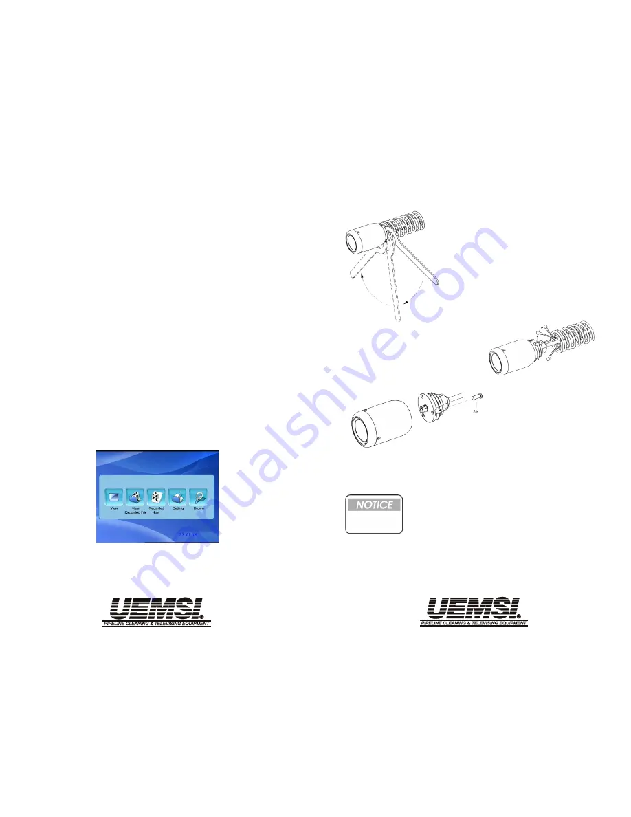
Camera Head Removal (Spring Termination)
3
Use a screwdriver to
remove the three combi-
nation screws that fasten
the camera head to the
cable/connector end.
(Fig. 3).
1
To detach the camera head
from front spring connector,
hook the spanner wrench
onto the end of the spring.
Simultaneously, rotate the
spanner wrench and camera
head in opposite directions.
(Fig. 1)
2
Release tow cable ends
(Fig. 2), allowing the spring
to be pushed away from the
camera head.
Figure 1
Figure 2
Figure 3
Slide the camera head off of the connector. Pay particular
attention to the O-ring, check it for wear and for proper
alignment.
-26-
4


