UDO Super 6 — Owner’s Manual
90
USING THE MODULATION MATRIX
The top raised panel and the keyboard model’s performance control
section as well as the desktop model’s LFO 2 section provide you with a
lot of options for assigning a variety of modulation sources to a number
of different modulation destinations. You can further extend these
capabilities by using the Super 6’s modulation matrix. The modulation
matrix is accessed via the patch button section, and there are two different
methods to map modulation routings, which will be described below.
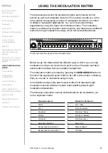
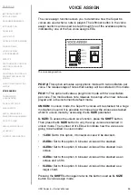
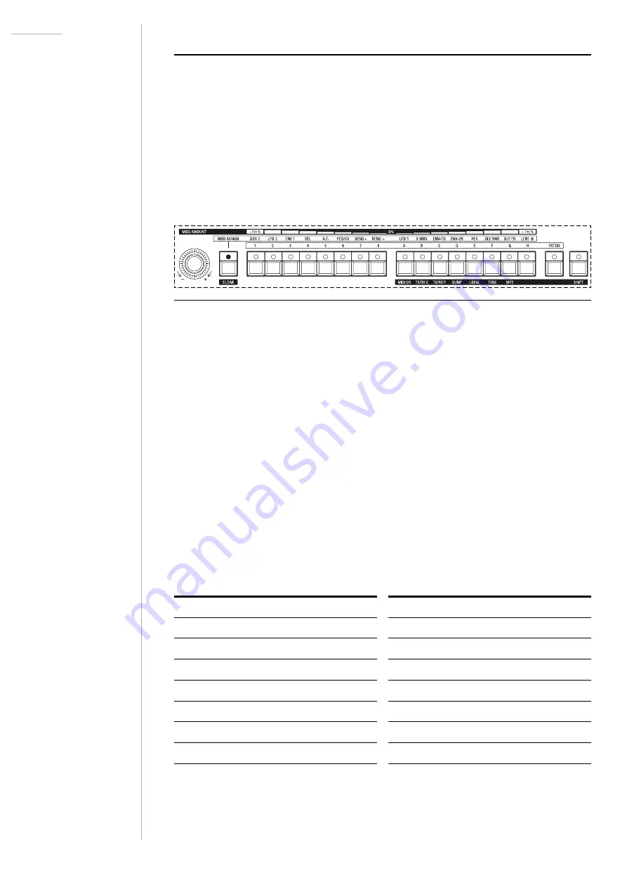
The front panel section relevant to the modulation matrix.
Before we go into detail about the different ways in which you can map
modulation routings, we would like to point out how the patch and bank
select buttons behave during modulation assignment.
The modulation matrix is entered by pressing the
MOD ASSIGN
button to
the left of the eight patch select buttons. Its LED will then flash, indicating
that you are now in modulation assign mode.
In modulation assign mode patch select buttons
1
-
8
represent eight
modulation sources while bank select buttons
A
-
H
represent eight
modulation destinations.
The following modulation sources and destinations are available to you
on the keyboard model:
Modulation Source
Modulation Destination
1
DDS 2
A
LFO 1 Rate
2
LFO 2
B
Cross Modulation
3
Envelope 1
C
Envelope 1 Decay
4
Velocity
D
Envelope 2 Release
5
Aftertouch
E
Filter Resonance
6
Expression Pedal/CV
F
Delay Time
7
Bender pushed to the left (-)
G
Delay Feedback
8
Bender pushed to the right (+)
H
LR Phase

