


Yudian (H.K.) Automation Technology Co. Ltd.
Website:
http://www.yudian.us
http://www.yudian.com.hk
Email:
Tel: +852-2770
8785 Fax: +852-2770 8796
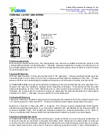
TERMINAL LAYOUT AND WIRING
注:本图为
A
、
C
、
E
型竖
式面板的式仪表接线图。
本图顺时针旋转
90
度后
为
B
、
F
型横式面板仪表
的接线图,端子编号不
变。
AU1
M1
M2/MIO
AUX
ALM
COMM
AL2
1
2
3
4
5
6
7
8
9
10
11
12
15
16
17
18
19
20
13
14
AL1
AU2
COM
COM
N/C
N/O
N/O
N/O
+
+
A
B
+
100-240VAC~
+
+
OUTP/M3
COM
COM
N/O
N/C
N/O
N/O
COM
N/C
N/O
+
+
COM
COM
N/O
N/O
N/O
N/C
+
+
IN3
IN2
IN1
CJC
+
+
OP2/IN6
OP1/IN5
IN4
IN3
IN2
IN1
This graph is for upright
instruments with
dimension A, C, E.
For instruments with
dimension B, F , just
clockwise rotate the
graph for 90 degree,
and the terminal
numbers keep
unchanged.
AU1
M1
M2/MIO
AUX
ALM
COMM
AL2
1
2
3
4
5
6
7
8
9
10
11
12
15
16
17
18
19
20
13
14
AL1
AU2
COM
COM
N/C
N/O
N/O
N/O
+
+
A
B
+
100-240VAC~
+
+
OUTP/M3
COM
COM
N/O
N/C
N/O
N/O
COM
N/C
N/O
+
+
COM
COM
N/O
N/O
N/O
N/C
+
+
IN3
IN2
IN1
CJC
+
+
OP2/IN6
OP1/IN5
IN4
IN3
IN2
IN1
Thermocouple wiring:
When wiring a thermocouple input, the compensation wire should be qualified and directly connect to the
corresponding terminals in correct direction. When M1 module is installed in J1 socket, a Cu50 resistor can
be connected between terminal 17 and 20 to compensate the cold junction; short terminal 17 and 20 to have
ice-point compensation.
Two-wire RTD wiring:
RTD can select two-wire or three-
wire method by B of “AF” parameter. Two
-wire method accepts input two
channel signals in one module, but user has to measure and calculate the resistance of the wire. To apply
two-wire method, J2 module should be installed and resistance of each wire should be less than 2ohm.
AI-702M/704M/706M can measure the lead wire resistance of two-
wire method and save it to parameter “Sc”.
However, the lead wire resistance changes as the temperature changes. If the lead wires has the same
ambient temperature as that of the instrument and no other resistor series connects to the lead wire, the
indicators can compensate the resistance change by measuring the ambient temperature (compensation
coefficient is 0.004/
★
); otherwise, two-wire method is not recommended.
Three-wire RTD wiring:
Three-wire method is a traditional wiring method requiring that the resistance of the three wires be equal. One
“J0
”
module supports 1 three-wire RTD. Three-wire method provides higher measurement accuracy.
Maximum 3 channel of three-wire RTD is accepted. The channel number automatically shifts forward,
affecting the parameter application. E.g. J0 module is installed in M1 and M2 slot for two three-wire RTD. J2
module is installed in M3. This implies the instrument accept four channels (Parameter: Cn=4, AF.B=1).
There is no IN5 and IN6. Three-wired RTD is recommended to install in prior slot to avoid confusion.
Two-wire retransmission input:
AI-702M/704M/706M internally provide 24VDC power, maximum 90mA, for up to 4 two-wire transmitters. J5
module can directly be connected to two-wire transmitter. Each instrument is recommended to install not
more than two J5 or V24 modules, otherwise the instrument may be failed to power on because of overload.
Certain measurement error occurs due to they are commonly grounded as well. If more retransmission is