


Doc. 85588U - Rev. 22/10/2020
USER MANUAL
USER MANUAL
EN
EN
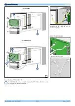
Drw. 32367/h
4/54
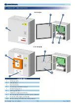
This manual is an integral part of C-SV 4A/8A and C-SV IB 4A/8A control units and it must be carefully read before using
it since it gives important indications with regards to its safe installation, use and maintenance. Keep it with care.
1. GENERAL SAFETY RULES
Before using C-SV 4A/8A and C-SV IB 4A/8A control units, read carefully the following general safety rules.
•
After taking off the packaging make sure that the control unit is intact. In case of doubt do not use it and contact an authorized
service centre.
•
Check that the control unit is not damaged in any of its parts. The safety concept of the control unit is valid only in perfect
conditions.
RISK OF ELECTRICAL SHOCKS
•
Any damaged socket, connection terminal or cable must be replaced immediately by qualified technicians or by authorized
service centre.
•
In case of repair or replacement of the connection cables and/or of the damaged devices or that don’t work properly, please
contact the
authorized service centre.
•
Incorrect or improper installation may cause the system to malfunction and/or result in damage to people and/or property.
•
Always disconnect the power supply before opening the control unit.
Any installation and/or maintenance tasks are only to be carried out by skilled, specialist personnel.
Existing electrical systems must comply with the rules in force in the country where the control unit is installed.
Before doing any maintenance, make sure that the power supply and the batteries have been disconnected.
Install an all-pole disconnecting device in the power supply system (IEC EN 60335-1).
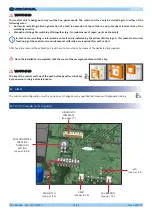
Conform to the “ELECTRICAL CONNECTIONS” wiring diagrams shown in this manual.
1.1 Symbols used
The operations which can be dangerous if they are not carried out correctly are indicated with this symbol.
Danger to persons due to electricity.
The operations whose execution requires qualified or specialized staff to avoid any danger are indicated with this symbol.
Important information for a correct installation and use of the product.
Содержание C-SV 4A
Страница 2: ......
Страница 25: ...Doc 85588U Rev 22 10 2020 USER MANUAL USER MANUAL EN EN Drw 32367 h 25 54 NOTES...
Страница 26: ......
Страница 54: ...Doc 85588U Rev 22 10 2020 USER MANUAL MANUALE D USO USER MANUAL MANUALE D USO EN IT EN IT Drw Dis 32367 h 54 54...
Страница 55: ......


