


Doc. 85588U - Rev. 22/10/2020
USER MANUAL
USER MANUAL
EN
EN
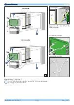
Drw. 32367/h
15/54
8. USE
8.1 Commands and signals
This control unit is designed to stay switched on permanently. The control unit can only be started again in either of the
following cases:
•
Automatic restarting following detection of a fault in execution of the software, and subsequent intervention of the
watchdog circuitry.
•
Manual restarting after switching off altogether (e.g. for maintenance of repair works on the plant).
In both cases, restarting is interpreted as a fault and is indicated by the yellow LED staying on. This means that correct
functioning of the control unit and subsequent calibration are required after each restart.
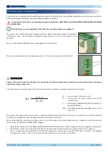
WARNING
WARNING
After having carried out the calibration, close the control unit door by means of the dedicated key supplied.
The control unit configuration must be carried out / changed only by qualified technicians with adequate training.
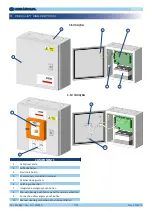
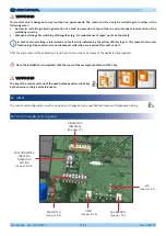
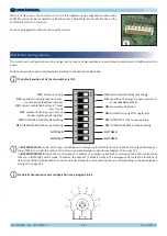
POTENTIOMETER
FOR WIND
THRESHOLD
SETTING
(see par. 8.4.4)
RESET
(see par. 8.3.6)
CALIBRATION
(see par. 7.3)
LED
(see par. 8.1)
DIP-SWITCH
(see par. 8.2)
DIAGNOSTIC
INTERFACE
(see page 17)
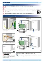
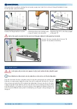
The key of the control unit and of the push button panel must be kept
by the person in charge of maintenance.
WARNING
WARNING
Once the installation is completed, lock the cover of the emergency button with the key.
Содержание C-SV 4A
Страница 2: ......
Страница 25: ...Doc 85588U Rev 22 10 2020 USER MANUAL USER MANUAL EN EN Drw 32367 h 25 54 NOTES...
Страница 26: ......
Страница 54: ...Doc 85588U Rev 22 10 2020 USER MANUAL MANUALE D USO USER MANUAL MANUALE D USO EN IT EN IT Drw Dis 32367 h 54 54...
Страница 55: ......


