EVK-NINA-B4 - User guide
UBX-19054587 - R04
Board configuration
Page 14 of 40
C1 - Public
4
Board configuration
4.1
Powering options
Power can be supplied to the board in any of the following ways:
•
Via any of the USB connectors, J8 or J16
•
Using the power jack, J5
•
Using the Arduino interface VIN or 5V pin, J1.8 or J1.5
•
Using the Raspberry Pi interface 5V pins, J14.2 or J14.4
•
Using the pin header J17
•
Plugging in a battery to the battery holder BT1
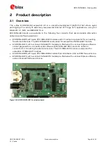
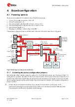
These power supply sources are distributed to the rest of the board as shown in Figure 6.
Figure 6: Block diagram of the power net distribution
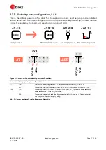
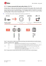
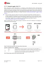
Selecting the power configuration jumpers
EVK-NINA-B4 offers flexible powering options for the NINA-B4 module and the board itself. To
configure this, jumpers are added or removed to pin headers, shorting two of the pins together and
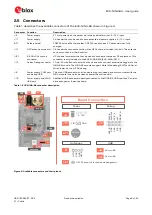
connecting or disconnecting different power nets on the evaluation board. Figure 7 shows an overview
of the available power sources and targets. Figure 8 shows the location of the power configuration
jumper headers.
⚠
Check the jumper positions carefully. If any jumper is connected in a wrong way, it can
permanently damage the components that are ON or connected to the board. Note also that
some jumpers should not be mounted simultaneously.
Diode protection
3.3 V
DC/DC
Regulator
Fuse
5 V
3.3 V
Diode protection
3 V
2.7 V
J7
Power select
jumper header
J22
NINA power select
jumper header
VDD_NINA
3.3 V
3.3 V
VIN
1.7 - 3.6 V
external supply
J1 and J14
Arduino and
Raspberry Pi
pin headers
VCC
VCC_IO
VDD_IO
NINA
Module
Board
peripherals
BT1
CR2032
3 V
J5
5 - 12 V
J8
5 V
J16
5 V
J17 pin 2
VIN pin header
5 - 12 V
J1 pin 8
Ardunio VIN pin
5 - 12 V
Diode protection
USB
conn.
Batt.
holder
Power
jack
USB
conn.

