background image

6

mFi

 mPort

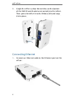
3.  Angle the mPort so that the notches on the bottom 

of the Wall-Mount Bracket are inserted into the mPort. 
Then press the mPort into the Release Tabs and snap 
it into place.

Connecting Ethernet

1.  Connect an Ethernet cable to the Ethernet port on the 

mPort.

Содержание mFi mPort

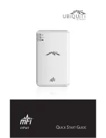
Страница 1: ...mPort ...

Страница 2: ......

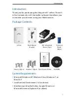
Страница 3: ...Bracket PoE Adapter Power Cord Terminal Block Male mPort Application Support Windows XP Windows Vista Windows 7 Mac OS X mFi Controller Software Quick Start Guide Version 1 0 Screws Qty 4 Anchors Qty 4 Quick Start Guide CD ROM System Requirements Microsoft Windows XP Windows Vista Windows 7 or Mac OS X Java Runtime Environment 1 6 or above Web Browser Mozilla Firefox Google Chrome or Microsoft Int...

Страница 4: ...eady green when an active Ethernet connection is made and flash when there is activity Status The Status LED will light yellow when the mPort is first powered on in factory default mode out of the box The Status LED will light steady green when the mPort has been successfully integrated into a network and is working properly The Status LED will flash when the Locate button is used in the mFi Contr...

Страница 5: ...3 Hardware Overview Side View mFi RJ45 Ports mFi Terminal Block Port USB Port Ethernet Port Wall Mount Bracket The USB Port is reserved for future use ...

Страница 6: ...4 mFi mPort Hardware Installation Remove the Wall Mount Bracket from the mPort by pressing the Release Tabs Release Tabs ...

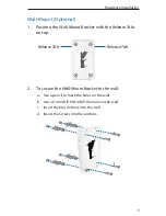
Страница 7: ...t with the Release Tabs on top Release Tab Release Tab 2 To secure the Wall Mount Bracket to the wall a Use a pencil to mark the holes on the wall b Use a 6 mm drill bit to drill the holes in the wall c Insert the four Anchors into the wall d Insert the Screws into the anchors ...

Страница 8: ... that the notches on the bottom of the Wall Mount Bracket are inserted into the mPort Then press the mPort into the Release Tabs and snap it into place Connecting Ethernet 1 Connect an Ethernet cable to the Ethernet port on the mPort ...

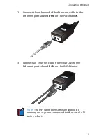
Страница 9: ...rnet cable to the Ethernet port labeled POE on the PoE Adapter 3 Connect an Ethernet cable from your LAN to the Ethernet port labeled LAN on the PoE Adapter Note The mFi Controller software should be running on a system connected to the same LAN as the mPort ...

Страница 10: ...the PoE Adapter Connect the other end of the power cord to a power outlet The Power LED should light up on the mPort Software Installation Insert the mFi Controller software CD into your CD ROM drive and follow the instructions for your specific computer type ...

Страница 11: ...9 Software Installation Mac Users 1 Click the Install icon 2 Click Continue and follow the on screen instructions to install the software ...

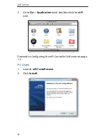
Страница 12: ...10 mFi mPort 3 Go to Go Applications and double click the mFi icon Proceed to Configuring the mFi Controller Software on page 12 PC Users 1 Launch mFi installer exe 2 Click Install ...

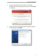
Страница 13: ...allation 3 If your computer doesn t have Java 1 6 or above installed you will be prompted to install it Click Install to continue 4 Ensure the Start mFi Controller after installation option is checked and click Finish ...

Страница 14: ...ort Note The mFi Controller software can also be launched from Start All Programs Configuring the mFi Controller Software 1 The mFi Controller software startup will begin Click Launch a Browser to Manage Network ...

Страница 15: ... appear the first time you launch the mFi Controller software On the Welcome screen select your language and country Click Next 3 Select the device s that you want to configure The Refresh button can be used to refresh the list of devices Click Next to continue ...

Страница 16: ...14 mFi mPort 4 Enter an administrator name in the Admin Name field Enter a password in the Password and Confirm fields Click Next 5 Click Finish to confirm your settings ...

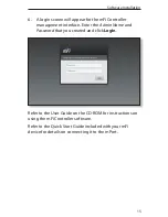
Страница 17: ...nagement interface Enter the Admin Name and Password that you created and click Login Refer to the User Guide on the CD ROM for instructions on using the mFi Controller software Refer to the Quick Start Guide included with your mFi device for details on connecting it to the mPort ...

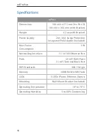
Страница 18: ...e Protection Integrated PoE Adapter Included Max Power Consumption 3 W Networking Interface 1 10 100 Ethernet Port Ports 2 mFi RJ45 Ports 1 mFi Terminal Block Port WiFi Standards 802 11b g n Memory 16 MB RAM 8 MB Flash LEDs 3 LEDs Power Ethernet Status Mounting Wall Mount Bracket Included Operating Temperature 10 to 70 C Operating Humidity 5 to 80 Condensing ...

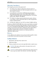
Страница 19: ...ng usage or trade practice with respect to the products Repair or replacement in the manner provided herein shall be the sole and exclusive remedy of Buyer for breach of warranty and shall constitute fulfillment of all liabilities of UBIQUITI NETWORKS with respect to the quality and performance of the Products UBIQUITI NETWORKS reserves the right to inspect all defective Products which must be ret...

Страница 20: ...ETWORKS does not warrant that the operation of the products is error free or that operation will be uninterrupted In no event shall UBIQUITI NETWORKS be responsible for damages or claims of any nature or description relating to system performance including coverage buyer s selection of products for buyer s application and or failure of products to meet government or regulatory requirements Returns...

Страница 21: ...connection to a grounded safety outlet a Do not substitute the power cord with one that is not the provided approved type Never use an adapter plug to connect to a 2 wire outlet as this will defeat the continuity of the grounding wire b The equipment requires the use of the ground wire as a part of the safety certification modification or misuse can provide a shock hazard that can result in seriou...

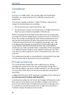
Страница 22: ...ause harmful interference to radio communications Operations of this equipment in a residential area is likely to cause harmful interference in which case the user will be required to correct the interference at his own expense The professional installer is responsible for ensuring that the system is used exclusively for fixed point to point operations RF Exposure Warning The transceiver described...

Страница 23: ... Industrie Canada Dans le but de réduire les risques de brouillage radioélectrique à l intention des autres utilisateurs il faut choisir le type d antenne et son gain de sorte que la puissance isotrope rayonnée équivalente p i r e ne dépasse pas l intensité nécessaire à l établissement d une communication satisfaisante CE Marking CE marking on this product represents the product is in compliance w...

Страница 24: ...irektiivin 1999 5 EY oleellisten vaatimusten ja sitä koskevien direktiivin muiden ehtojen mukainen Français French Par la présente UBIQUITI NETWORKS déclare que l appareil UBIQUITI NETWORKS device est conforme aux exigences essentielles et aux autres dispositions pertinentes de la directive 1999 5 CE Deutsch German Hiermit erklärt UBIQUITI NETWORKS dass sich diese UBIQUITI NETWORKS device in Übere...

Страница 25: ...F Slovensky Slovak UBIQUITI NETWORKS t mto vyhlasuje e UBIQUITI NETWORKS device sp a základné po iadavky a v etky príslu né ustanovenia Smernice 1999 5 ES Svenska Swedish Härmed intygar UBIQUITI NETWORKS att denna UBIQUITI NETWORKS device står I överensstämmelse med de väsentliga egenskapskrav och övriga relevanta bestämmelser som framgår av direktiv 1999 5 EG Español Spanish Por medio de la prese...

Страница 26: ...etails visit www ubnt com mfi Ceiling Mount Motion Sensor mFI MSC Wall Mount Motion Sensor mFi MSW Temperature Sensor mFi THS Current Sensor mFi CS Door Sensor mFi DS Thermostat Coming Soon 1 2 3 1 2 3 4 5 6 7 8 mPort Serial mPort S Power Adapter mPower Mini Power Strip mPower Power Strip mPower Pro RRJL073012 ...

Страница 27: ......

Страница 28: ...t Email support ubnt com Phone 9 a m 5 p m PST 408 942 1153 Online Resources Wiki Page wiki ubnt com Support Forum forum ubnt com Downloads downloads ubnt com w w w u b n t c o m 2012 Ubiquiti Networks Inc All rights reserved ...

Отзывы: