background image

20

airFiber AF-24 Quick Start Guide

Alignment

Tips

•  Fine-tuning is best achieved by a pair of installers with a 

dedicated, two-way communication link: one installer makes 

adjustments on one airFiber radio while the other installer 

reports the received signal level at the other airFiber radio. 

Fine-tuning (see Fine-Tuning the Link) is necessary because 

the main lobe of the receiver is narrower than that of the 

transmitter, in both azimuth and elevation.

•  To accurately align the airFiber radios for best performance, you 

MUST align only one end of the link at a time.

•  For more convenient alignment, you may consider using 

long-range scopes (not included) temporarily attached to your 

airFiber radios.

•  You may need to use additional hardware to compensate for 

issues such as the improper orientation of a mounting pole or 
significant elevation differences between the airFiber radios.

Establishing a Preliminary Link

Adjust the positions of the Master and the Slave to establish a 
preliminary link. This requires the Master and Slave to be within a 
few degrees of the line of sight between the airFiber radios.

Note:

 The Master must be aimed first at the Slave because 

the Slave does not transmit any RF signal until it detects 
transmissions from the Master.

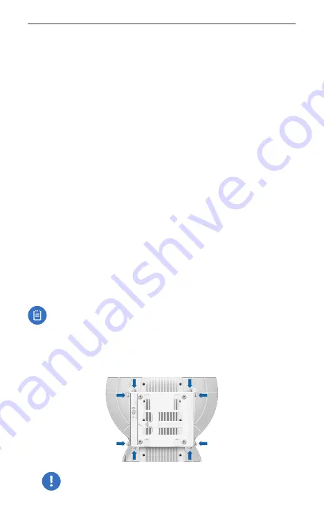
1.  For the Master and Slave, ensure the eight Lock Bolts on the 

Alignment Bracket are sufficiently loose by spinning each 

washer by hand.

WARNING:

 All Lock Bolts MUST be loose to avoid 

damage to the airFiber housing.

Содержание airFiber AF-24-US

Страница 1: ...24 GHz Point to Point 1 4 Gbps Radio Model AF 24...

Страница 2: ......

Страница 3: ...ashers Qty 4 Hex Nuts Qty 4 24 GHz Point to Point 1 4 Gbps Radio Model AF 24 GigE PoE Adapter 50V 1 2A Power Cord airFiber AF 24 Quick Start Guide TERMS OF USE Ubiquiti radio devices must be professio...

Страница 4: ...2 airFiber AF 24 Quick Start Guide Hardware Overview Side Alignment Bracket Elevation Adjustment Azimuth Adjustment Ground Bonding Point Lock Bolts Lock Bolts...

Страница 5: ...3 Hardware Overview Back Lock Bolts Lock Bolts Azimuth Adjustment 24 GHz Lock Bolts Lock Bolts Cover Lock Elevation Adjustment Port Cover...

Страница 6: ...le the unit is powered on Data 10 100 1000 Mbps port handles all user traffic Aux Port for audio tone aiming LED Display Digital display used for power status and mode information Config 10 100 Mbps s...

Страница 7: ...Normal Flash 4x 16QAM MIMO Long Flash 6x 64QAM MIMO LED Display RX Power dBm Number Decodable RX Signal Flashing Number Undecodable RX Signal Overload Condition Master Slave Off Slave Mode On Master...

Страница 8: ...Note For guidelines about grounding and lightning protection follow your local electrical regulatory codes Outdoor shielded Category 5e or above cabling and shielded RJ 45 connectors should be used f...

Страница 9: ...move the airFiber radios Reconnect at the site After you have mounted the airFiber radios establish and optimize the RF link Connecting Power over Ethernet 1 Turn the Cover Lock to the Unlocked icon S...

Страница 10: ...AF 24 Quick Start Guide 3 Connect the Ethernet cable from the Data port to the POE port on the GigE PoE Adapter 4 Connect the Power Cord to the GigE PoE Adapter and then plug the Power Cord into a po...

Страница 11: ...ing options at the cost of higher latency and throughput Full duplex operation provides the highest throughput and lowest latency however you have fewer frequency management options Half Duplex defaul...

Страница 12: ...or example 192 168 1 100 3 Launch your web browser Type http 192 168 1 20 in the address field and press enter PC or return Mac http 192 168 1 20 4 The login screen will appear Enter ubnt in the Usern...

Страница 13: ...h the Master and the Slave c For the Duplex drop down Half Duplex The default mode The TX and RX Frequencies can be the same or different to suit local interference Full Duplex The TX and RX Frequenci...

Страница 14: ...z 8 Click Change and then click Apply 9 In Band Management is enabled by default so each airFiber radio must have a unique IP Address If the airFiber radios use the same IP Address then you may lose...

Страница 15: ...Bracket to a pole Note The mounting assembly can accommodate a 51 101 mm 2 0 4 0 pole a Orient the Pole Mount Bracket around the pole so it is aimed in the direction of the other airFiber AF 24 b Ins...

Страница 16: ...24 Quick Start Guide 3 Loosen but do NOT remove the eight Lock Bolts located on the Alignment Bracket 4 Ensure that there is a 6 mm gap between the head of each Serrated Flange Screw and the Alignmen...

Страница 17: ...rFiber AF 24 and align the four Serrated Flange Screws with the slots on the Pole Mount Bracket Seat the screws in the slots Securely tighten the screws WARNING To prevent injury ensure that all four...

Страница 18: ...min 8 AWG or 10 mm2 to the lug and replace the nut to secure the wire c Secure the other end of the ground wire to a grounded mast pole tower or grounding bar WARNING Failure to properly ground your a...

Страница 19: ...Slide the Port Cover down to remove it 24 GHz 2 Connect a TOUGHCable or other outdoor shielded CAT5e 6 cable to the Data port 3 Create a strain relief for the Ethernet cable by feeding a Cable Tie thr...

Страница 20: ...the GigE PoE Adapter 6 Connect the Power Cord to the PoE Adapter and then plug the Power Cord into a power outlet Note For added protection we recommend installing two GigE PoE surge protectors Insta...

Страница 21: ...shed installation with recommended surge protectors installed Ground to Pole Tower or Grounding Block Max 1 m from Ground Bonding Point Max 1 m Outdoor GigE PoE Surge Protector EdgeRouter GigE PoE Ada...

Страница 22: ...opes not included temporarily attached to your airFiber radios You may need to use additional hardware to compensate for issues such as the improper orientation of a mounting pole or significant eleva...

Страница 23: ...ion on the pole a Loosen the Hex Nuts b Adjust the Pole Mount Bracket and Pole Clamps c Tighten the Hex Nuts Hex Nuts 4 Slave Aim the Slave at the Master to achieve the strongest received signal level...

Страница 24: ...zimuth AZ Adjustment Bolt of the Master through its adjustment range Master Azimuth AZ Adjustment Bolt b Sweep the Elevation EL Adjustment Bolt of the Master through its adjustment range Master Elevat...

Страница 25: ...he Master until the other installer sees the strongest received signal level displayed on the LED Display of the Slave 3 Repeat steps 1 and 2 until you achieve a symmetric link with the received signa...

Страница 26: ...Fiber Configuration Interface and audio tone methods The User Guide is available at www ubnt com download airfiber Installer Compliance Responsibility Devices must be professionally installed and it i...

Страница 27: ...Data Port Configuration Port 1 10 100 1000 Ethernet Port 1 10 100 Ethernet Port Mounting Pole Mount Kit Included Wind Loading 306 9 N 200 km hr 69 lbf 100 mph Operating Temperature 40 to 55 C 40 to 13...

Страница 28: ...Service should be provided only by a qualified service technician 3 This equipment is provided with a detachable power cord which has an integral safety ground wire intended for connection to a ground...

Страница 29: ...ks authorized representatives or as approved by Ubiquiti Networks in writing II has been painted rebranded or physically modified in any way III has been damaged due to errors or defects in cabling IV...

Страница 30: ...NESS FOR A PARTICULAR PURPOSE AND NON INFRINGEMENT AND ANY WARRANTIES ARISING FROM ANY COURSE OF DEALING USAGE OR TRADE PRACTICE IN CONNECTION WITH SUCH PRODUCTS AND SERVICES BUYER ACKNOWLEDGES THAT N...

Страница 31: ...clusions of implied warranties or conditions so the above exclusion may not apply to you You may have other rights that vary from country to country state to state or province to province Some countri...

Страница 32: ...nterference when the equipment is operated in a commercial environment This equipment generates uses and can radiate radio frequency energy and if not installed and used in accordance with the instruc...

Страница 33: ...suivantes 1 l appareil ne doit pas produire de brouillage 2 l appareil doit accepter tout brouillage radio lectrique subi m me si le brouillage est susceptible d en compromettre le fonctionnement Le...

Страница 34: ...R HR HU IE IT LV LT LU MT NL PL PT RO SE SI SK UK BFWA Broadband Fixed Wireless Access members noted in blue Note This device meets Max TX power limit per ETSI regulations The following apply to produ...

Страница 35: ...d elektronische Ger te ber die daf r zust ndigen und von der Regierung oder rtlichen Beh rden dazu bestimmten Sammelstellen zu entsorgen Ordnungsgem es Entsorgen und Recyceln tr gt dazu bei potentiell...

Страница 36: ...es pouvoirs publics locaux le service de traitement des d chets ou l endroit o vous avez achet le produit Italiano La direttiva europea 2012 19 UE richiede che le apparecchiature contrassegnate con qu...

Страница 37: ...i keel Estonian K esolevaga deklareerib UBIQUITI NETWORKS et k esolev raadioseadme t p AF 24 vastab direktiivi 2014 53 EL n uetele ELi vastavusdeklaratsiooni t ielik tekst on k ttesaadav j rgmisel int...

Страница 38: ...pny pod nast puj cym adresem internetowym www ubnt com compliance Portugu s Portuguese O a abaixo assinado a UBIQUITI NETWORKS declara que o presente tipo de equipamento de r dio AF 24 est em conformi...

Страница 39: ......

Страница 40: ...demarks or registered trademarks of Ubiquiti Networks Inc in the United States and in other countries All other trademarks are the property of their respective owners Support help ubnt com Community c...

Отзывы: