background image

4440 Creek Road • Cincinnati, Ohio 45242 USA

National Phone: 1-800-252-4647

Telephone: (513) 891-0400 • Fax: (513) 891-4882

www.uasinc.com

UNITED AIR SPECIALISTS, INC.

LIMITED WARRANTY

UAS  warrants  to  the  original  purchaser  that  all  equipment  will  be  free  from  defects  in  materials  and 

workmanship for one year from the date of shipment from UAS (three years for Smokeeter® and VisionAir™ 

models other than CC and DC series) and that major structural components on SFC and MCB series will be 

free from defects in materials and workmanship for ten years from the date of shipment from UAS.  This 

warranty applies only if equipment is properly installed, maintained, and operated under normal conditions 

and does not apply to damage caused by corrosion, abrasion, abnormal use or misuse, misapplication, or 

normal wear and tear.  This warranty will be void with respect to equipment that is subject to unauthorized 

repairs or modifications.  UAS makes no warranty as to goods manufactured or supplied by others.  This 

warranty  is  subject  to  any  limitations  in  UAS’  quotation  and  may  not  be  modified  except  by  a  written 

instrument signed by the President or Vice President of Sales of UAS.
THIS  WARRANTY  IS  EXCLUSIVE  AND  IN  LIEU  OF  ALL  OTHER  WARRANTIES,  WHETHER 

WRITTEN, ORAL OR IMPLIED, INCLUDING ANY IMPLIED WARRANTY OF MERCHANTABILITY, 

FITNESS FOR A PARTICULAR PURPOSE OR NONINFRINGEMENT.
As  Purchaser’s  exclusive  remedy  for  any  defects  in  the  equipment,  UAS  will  exchange  or  repair  any 

defective parts during the warranty period, provided such parts are returned, prepaid, to UAS’ factory.  The 

obligation of UAS is limited to furnishing replacement parts F.O.B. UAS’ factory or making repairs at UAS’ 

factory of any parts that are determined, upon inspection by UAS, to be defective.  In no event will UAS be 

responsible for labor or transportation charges for the removal, reshipment or reinstallation of the parts.
IN  NO  EVENT  WILL  UAS  BE  RESPONSIBLE  FOR  ANY  SPECIAL  OR  CONSEQUENTIAL 

DAMAGES.
WARRANTY REGISTRATION: Register online at www.uasinc.com/registration.aspx

©2016 United Air Specialists

Part No. 44-10643

REV: 17F

Содержание SMOGHOG SHM-05C

Страница 1: ...Model SHM 05C Shown SMOGHOG Media Mist Collector l Models SHM 05C SHM 08C OWNER S MANUAL ...

Страница 2: ... following information available when contacting UAS UAS ORDER _________________________________________________________________ UNIT MODEL ________________________________________________________________ UNIT SERIAL _________________________________________________________________ SYSTEM ACCESSORIES ______________________________________________________________________________ ___________________...

Страница 3: ...act 11 3 6 Filter Installation 11 3 6 1 Installation Procedure for After Filters 11 3 7 Drains 13 4 UNIT OPERATION 13 4 1 Start up 13 4 2 System Operation 13 4 2 1 Advanced Unit Operation 13 4 2 1 1 Airflow Adjustment Using Manual Speed Control 13 4 2 1 2 Airflow Adjustment Using Auto Flow Control 13 4 3 Touchscreen Operation 14 4 3 1 Start Up And Home Screen 14 4 3 2 Standard Format 14 4 3 3 Basi...

Страница 4: ...terials and vapors such as gasoline away from the unit The unit should be inspected frequently and contaminants removed to prevent excessive accumulation which may result in flash over or fire damage Operate only in a safe and serviceable condition Operating temperature to the air stream should not exceed 120 F 49 C DANGER WARNING WARNING CAUTION C A U T I O N This is the safety alert symbol This ...

Страница 5: ...gs will also be included If you require assistance in the installation startup operation maintenance or troubleshooting of your air cleaning equipment contact your local UAS sales representative 2 1 SMOGHOG NOMENCLATURE SMOGHOG oil mist air cleaners are available in a variety of configurations and sizes The model string for each given unit represents the base configuration The model number complet...

Страница 6: ...REV 17F SMOGHOG SHM Series Models 2 FIGURE 1B SHM 05C Basic Equipment Description 61 10128 61 10128 FIGURE 1A SHM 05C Basic Equipment Description ...

Страница 7: ...REV 17F SMOGHOG SHM Series Models 3 FIGURE 1D SHM 08C Advanced Equipment Description FIGURE 1C SHM 08C Advanced Equipment Description 61 10129 61 10129 ...

Страница 8: ...s during operation The collected contaminate is drained off of the coalescing filters into the sump below The sump is attached to a drain system of the customers choice for recycling or disposal Do not let the oil level in the sump reach the height of the lower tubesheet where the filters rest Differential Pressure Differential pressure also referred to as pressure drop Δ P is an indication of the...

Страница 9: ...eering drawings of your specific equipment and options will be provided These and all available documentation for your system should be thoroughly reviewed prior to beginning any installation work This includes the unit and electrical controls Ensure to leave an appropriate amount of room around your unit to allow for maintenance and servicing A minimum of 3 feet 1 m of clearance is recommended fo...

Страница 10: ...Figure 1 for reference Ceiling mounted units are suspended by means of 1 2 threaded rods item 1 in Figure 3A which run through weld nuts item 2 in Figure 3A in the top corners of the units Refer to Figure 2 for weld nut locations on SHM models Additional support should be used for auxiliary equipment or ducting CAUTION The SMOGHOG should not be used for support of personnel or material Check with ...

Страница 11: ...REV 17F SMOGHOG SHM Series Models 7 FIGURE 3B Typical Machine Mount 61 10144 ...

Страница 12: ...he customers machine or a nearby wall Refer to figure 3B above for proper mounting locations and instructions Various wall mount brackets are offered and should be selected based on the desired orientation of the unit when fully assembled Left side shown right side same bracket rotated 180 and rear mounting is available ...

Страница 13: ... 3 60 3065 2 1 SHM 08C A 208 3 50 60 2600 3 6 SHM 08C A 230 3 50 60 2600 4 6 SHM 08C A 380 3 50 60 2600 2 3 SHM 08C A 460 3 50 60 2600 2 8 TABLE 2 Wiring Diagrams 3 5 1 ELECTRICAL SUPPLY POWER The main power supply is connected to the SHM unit through a customer sourced sealed 1 2 conduit connector that can be installed into the 7 8 hole next to the electrical box After feeding wires through the c...

Страница 14: ...REV 17F SMOGHOG SHM Series Models 10 61 10129 Figure 4 Remote Panel Touchscreen Connection ...

Страница 15: ...Machine Interlock set up on the touchscreen Wiring will be terminated to the terminal blocks located in the rear electrical panel in Figure 1D When the machine dry contact is closed the SHM blower will be on and when the contact is open the SHM unit blower will shut down Note A relay coil cannot be connected to the SHM and will not work for this type of electrical circuit 3 6 FILTER INSTALLATION T...

Страница 16: ...REV 17F SMOGHOG SHM Series Models 12 61 10133 Figure 5 SHM Filter Removal Installation ...

Страница 17: ...cord baseline performance parameters so the system can be reset in case of an upset condition or system change The recorded data should include the static pressure at each collection hood system amperage draw and filter pressure drop at a minimum any other key pieces of data critical to your process 9 To optimize system performance and extend filter life run the unit at the minimum airflow require...

Страница 18: ...ow After Filter monitoring or unique screens required for a special application These screens are based on customer order and loaded at the factory Figure 7 4 3 2 Standard Format The icon key Table 3 outlines the various icons that are used on the screen for various reasons and may indicate status or conditions The Home Settings and Information icons are shown at the bottom of most screens and wil...

Страница 19: ...ween 20 and 100 This will correspond to the percentage of blower capability The blower is capable of 2 600 RPM at 100 1 950 RPM for 75 1 300 RPM for 50 and 520 RPM for 20 These numbers are approximate and may display slightly differently on any given unit There is a minimum set point for speed which is 20 for the purposes of the blower design Information Screen Figure 10 The information screen wil...

Страница 20: ...tings are not password protected To select one of the items just touch the box with the item you want to make a change too The Locked Settings selection will allow the operator to select options of the system One option is Machine Interlock Process Control With Machine Interlock the operator can allow another device CNC machine center to turn the SHM on when the primary device is in operation When...

Страница 21: ... Settings group on the Customer settings screen Auto Flow is an option that is selected at time of order and loaded into the SHM at the factory The Auto Flow Settings will allow the unit to maintain a precise operating point based on a desired air volume The operator will select an air volume setting in the airflow set point box using the up down arrows or the selection box If the screen is change...

Страница 22: ...manual Always wear proper PPE including goggles dust mask and work gloves when installing or replacing filter elements Oil accumulated on the filter elements can result in irritation of the lungs skin and or eyes Remove used filter elements from the collector and dispose of properly in accordance with governing restrictions Be sure there is no excess oil or residue build up inside the primary filt...

Страница 23: ...ist in making sure the filters are fully inserted when the door is closed and secured 5 3 CONTAMINANT REMOVAL Manual draining of the sump itself should not be necessary unless no drain is used If this is the case be sure to drain the sump regularly If a drain bottle or similar is used this should also be checked and emptied regularly Be sure oil is not accumulating in any location that could cause...

Страница 24: ...ker Open rear panel on unit and switch breaker if necessary Loose or disconnected wires Inves gate wiring in the rear panel Disconnect is switched to OFF posi on Switch disconnect to ON posi on Improper source power Refer to data plate to verify required input power Screen Displayed Warning Possible Causes Recommended Solu ons Filter Cau on Filter is approaching max life Replace filter s soon Yello...

Страница 25: ...T LATCH 4 42 0168 FILTER CABINET DOOR GASKET 5 42 0080 TOP PANEL WHITE PTFE GASKET NOT SHOWN 42 1549 SEALANT 10 38 10145 BULKHEAD FITTING 5 16 OD TUBING NOT SHOWN 20 1280 FLEX TUBING CLEAR 3 16 X 5 16 6 39 0258 04 FILTER CABINET DOOR HINGE PIN NOT SHOWN 39 0258 02 HINGE PIN E CLIP 7 32 10069 SHM 08C MOTORIZED IMPELLER 230 460V 7 32 10075 SHM 05C MOTORIZED IMPELLER 230 460V 8 10 14131 INLET COVER P...

Страница 26: ...REV 17F SMOGHOG SHM Series Models 22 61 10134 Figure 22 ...

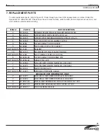
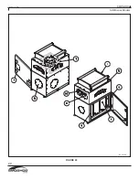
Страница 27: ...REV 17F SMOGHOG SHM Series Models 23 A1 BASIC UNIT 04 001990 ...

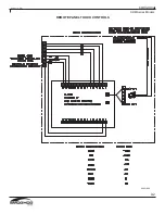
Страница 28: ...REV 17F SMOGHOG SHM Series Models 24 A2 REMOTE PANEL TOUCH CONTROLS 04 001802 ...

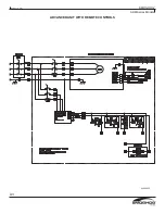
Страница 29: ...REV 17F SMOGHOG SHM Series Models 25 A3 ADVANCED UNIT WITH REMOTE CONTROLS 04 002235 ...

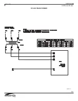
Страница 30: ...REV 17F SMOGHOG SHM Series Models 26 A4 575 480 TRANSFORMER 04 001717 ...

Страница 31: ...This page intentionally left blank ...

Страница 32: ... as to goods manufactured or supplied by others This warranty is subject to any limitations in UAS quotation and may not be modified except by a written instrument signed by the President or Vice President of Sales of UAS THIS WARRANTY IS EXCLUSIVE AND IN LIEU OF ALL OTHER WARRANTIES WHETHER WRITTEN ORALOR IMPLIED INCLUDINGANYIMPLIED WARRANTYOF MERCHANTABILITY FITNESS FOR A PARTICULAR PURPOSE OR N...

Отзывы: