background image

A-8

KING COBRA

®

 500 - 56041964

5/10

INSTRUCTIONS FOR USE

A - ENGLISH

SET-UP AND OPERATION

 CAUTION!

Use care when handling hazardous chemicals.
Never leave the machine running when you are not actively using it.
To avoid vacuum motor damage, always make sure the 

fl

 oat 

fi

 lter is clean and that it can travel freely before you operate the machine.  Always use a defoamer 

any time foam is present.

 DANGER!

Do NOT use solvents, or any chemicals that may be 

fl

 ammable, explosive or combustible.

CLEANING SOLUTIONS:

Select a proper pre-spray for the surface to be cleaned, and apply the pre-spray.  Use a neutral pH rinse or detergent (6 to 10 pH) in the King Cobra to prevent 
premature wear of the pumps, seals, and other components. Damage caused by the use of improper or strong chemicals is not covered by warranty.  Powdered 
chemicals are not recommended.

Before each use, inspect the machine, hoses, and cleaning tools for cleanliness and completeness.  Make sure the hoses are in good condition and the 
spray nozzle(s) is tight.  Be sure the Pre-Filter Bag 

(22 / KC-500-ADAF only)

 and the Dump Pump Inlet Filter 

(21)

 are installed and are clean.

KC-500-ADAF:

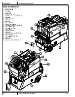
  When not using the auto-dump feature, just make sure the brass cap is screwed tightly on the Dump Hose Connection 

(16)

 on the dump 

pump on the rear of the machine.  If you choose to use the auto-dump, connect the dump hose to the Dump Hose Connection 

(16)

 on the back of the dump 

pump, and place the open end of the hose in a drain.  Make sure the Recovery Tank Drain Hose 

(15)

 is closed, and the Recovery Tank Lid 

(2)

 is closed tight.


REFER TO THE AUTO-FILL AND AUTO-DUMP INSTRUCTIONS ON THE FOLLOWING PAGES.

KC-500-ADAF:

  If you choose to use the auto-

fi

 ll feature, connect the 

fi

 ll hose to the Auto-Fill Hose Connector 

(7)

. Turn on the water source, and allow the 

tank to 

fi

 ll with water.  When using the auto-

fi

 ll system, the auto-

fi

 ll 

fl

 oat will automatically turn on and turn off as the tank empties and then 

fi

 lls.  

NOTE:

 If you 

are not going to use the auto-

fi

 ll system, just 

fi

 ll the tank with water and cleaning chemical. Follow chemical directions regarding dilution and mixing. Do not 

use harsh chemicals; they may damage seals in pumps and valves, and cause the pump to wear prematurely.


NOTE:

  Using warm water in the tank may improve the ef

fi

 ciency of the heat exchanger when cleaning with heat, but never use water with a temperature 

exceeding 130 °F / 54 °C.

Pre-spray the area to be cleaned, with a pump-up sprayer, while the tank is 

fi

 lling.  Follow chemical directions.

Plug in the power cords 

(17)

.  

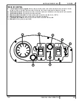
Do not connect both cords to the same outlet. The green, ‘separate circuit’ locator light 

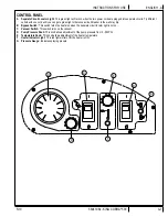
(A)

 on the switch plate should light 

up.  If the locator light does not come on, check the circuit breaker box in the wall, and/or try different outlets until it does turn on.  

  If you are certain the 

cords are on separate circuits, turn the Bypass switch 

(B)

 on. 


CAUTION:

 using the Bypass switch 

(B)

 when the cords are on the same circuit may cause the breaker in the wall to trip.  

NOTE:

 the 

receptacle 

(15)

 on the left (viewed from behind the machine) powers the heater.  


The red light 

(F)

 will turn on only when the heat exchanger is actively heating.

Press the lever on the Pressure Relief Valve 

(18)

 to make sure there is no back pressure in the system.

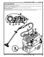
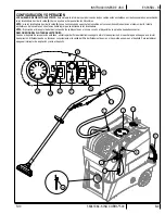
Connect the priming/siphon hose to the Solution Hose Quick Connect 

(6)

, turn the pump ON by turning the Pump Pressure Knob 

(D)

 up to increase pump 

speed and turn the Vacuum Switch 

(C)

 on.  Place the open end of the priming hose into the Vacuum inlet hose barb 

(1)

.  Use your hand to block the open 

area in the hose barb.  This will allow the pump and the vacuum to work together to get the water moving. The air should prime out of the pump within 20 - 
60 seconds.  Watch the water 

fl

 ow into the recovery tank.  When the water is clear (no air in it) and is 

fl

 owing strongly, turn both the pump and the vacuum 

off, and remove the priming hose.  NEVER remove the priming hose while the pump is still running.

Connect the Solution Hose 

(19)

 from the reel to the Solution Hose Quick Connect 

(6)

 and connect the Vacuum Hose 

(23)

 from the reel to the Vacuum Hose 

Connection 

(1)

. Connect both hoses to the cleaning tool.

Set the Temperature Knob 

(E)

 to the desired heat setting. Allow the heat exchanger two minutes to reach operating temperature.  The red light 

(F)

 will go out 

when the heater has reached operating temperature.  

NOTE:

  The red light will be on nearly all the time as you clean.

10  Turn the pump on by setting the Pump Pressure Knob 

(D)

 to the desired spraying pressure (0 - 500 PSI). Read the spraying pressure at the Pressure Gauge 

(G)

 while spraying.  

NOTE:

  when you let off the trigger on the wand, the pressure gauge reading will drop to 0 psi; however, the spraying pressure will 

remain at the level to which you have set it.  Turn the Vacuum Switch 

(C)

 ON. 

NOTE:

  the vacuum motor will start up slowly to prevent a large current surge.


KC-500-ADAF:  

Turn on the dump pump 

(25)

.  

NOTE:

  The dump pump will automatically turn on and turn off as the tank 

fi

 lls and then empties. It may take 

several cycles to heat the lines and the cleaning tool.

11  If you are not using the auto-

fi

 ll and auto-dump features, turn off both the pump 

(D)

 and vacuum 

(C)

 when the Holding Tank gets low, 

fi

 ll the Holding Tank, 

and empty and clean the recovery tank.

12 Begin 

cleaning.

13  Use defoamer in the recovery tank any time foaming occurs.
14 When 

fi

 nished with the job, remove any unused solution from the solution tank, and run a few gallons of clean water through the system.  Drain the recovery 

tank by placing the dump hose over a drain, or a bucket, and removing the cap. Disconnect the hoses from the cleaning tool, and reel them up onto the hose 
spool.

NOTE:

 To remove the reel, with hoses, from the machine, pull the vacuum hose loose from the hose barb on the front of the tank.  Disconnect the solution hose 

quick coupling.  Push Vacuum hose into the center of the hose spool.  Grasp the spool from either side, and lift it off the machine.  

NOTE:

  before servicing any 

component in the base cabinet, the hoses and spool must be removed from the machine before the tanks can be lifted open.

5/12

Содержание King Cobra KC-500

Страница 1: ...F THIS INSTRUCTION MANUAL PRECAUCI N NO UTILICE LA M QUINA HASTA HABER LE DO TODAS LAS SECCIONES DE ESTE MANUAL DE INSTRUCCIONES ATTENTION N UTILISEZ PAS LA MACHINE AVANT D AVOIR LU TOUTES LES SECTION...

Страница 2: ...ns A 5 Know Your Machine A 6 A 7 Control Panel A 7 Set Up and Operation A 10 A 11 Auto Fill A 12 Auto Dump A 12 After Use After Using the Machine A 13 Maintenance Maintenance Schedule A 13 Power Cord...

Страница 3: ...ne Use the space below to note the Model and Serial Number of your machine for future reference Model _________________________________________ Serial Number ___________________________________ UNPACK...

Страница 4: ...ped damaged left outdoors or dropped into water return it to a service center Do not pull by the cord use the cord as a handle close a door on the cord or pull the cord around sharp edges or corners D...

Страница 5: ...ominal 120 volt circuit and has a grounding plug that looks like the plug illustrated in Figure 1 below A temporary adapter illustrated in Figures 2 and 3 may be used to connect this plug to a 2 pole...

Страница 6: ...Quick Connect 7 Auto Fill Hose Connector KC 500 ADAF 8 Rear Wheel 9 Base Compartment 10 Holding Tank 11 Tank Latch 12 Vacuum Hose Reel 13 Recovery Tank Drain Hose 14 Dump Hose Connection KC 500 ADAF 1...

Страница 7: ...wise a circuit breaker in the wall may trip B Bypass Switch This switch turns the heater on when the separate circuit locator light is not on C Vacuum Switch This switch turns on the vacuum D Pump Pre...

Страница 8: ...may cause the breaker in the wall to trip NOTE the receptacle 15 on the left viewed from behind the machine powers the heater The red light F will turn on only when the heat exchanger is actively hea...

Страница 9: ...when the cords are plugged in then both cords are on the same circuit Try other outlets with one of the cords until you get the locator light to come on NOTE If the bypass switch is turned on when bo...

Страница 10: ...the ball float in the recovery tank is clean Attach a 3 4 garden hose to the Dump Hose Connection 14 on the dump pump on the back of the base of the machine Run the other end of the hose into a drain...

Страница 11: ...EDULE MAINTENANCE ITEM Daily Weekly Yearly Check Clean Tanks Hoses Check Clean Recovery Tank Shut Off Float Clean Extraction Wand Tool Inspect Clean Solution Filters Check Carbon Brushes IMPORTANT Mot...

Страница 12: ...ank is full and needs to be emptied All other KC 500 models Vacuum inlet screen may be plugged Remove and clean screen No power to motor s Test the switches Test the vacuum motors LOW HEAT Spraying to...

Страница 13: ......

Страница 14: ...uraci n y operaci n B 10 B 11 Llenado autom tico B 12 Vaciado autom tico B 12 Despu s de la utilizaci n Despu s de la utilizaci n de la m quina B 13 Mantenimiento Programa de mantenimiento B 13 Manten...

Страница 15: ...repuestos para la m quina Utilice el siguiente espacio para anotar el modelo y el n mero de serie de su m quina para futuras consultas Modelo ________________________________________ N mero de serie _...

Страница 16: ...utilice a modo de asa evite que el cable quede atrapado al cerrar una puerta y no tire de l contra bordes afilados ni esquinas No haga pasar la m quina por encima del cable Mantenga el cable alejado d...

Страница 17: ...e puede usar un adaptador provisorio tal como se ve en las Figuras 2 y 3 en caso de disponerse de un recept culo sin toma a tierra como en la Figura 2 Dicho adaptador provisorio se usar solamente hast...

Страница 18: ...era 9 Compartimento de base 10 Dep sito de retenci n 11 Pestillo del dep sito 12 Bobina del tubo de aspiraci n 13 Tubo de vaciado del dep sito de recuperaci n 14 Conexi n del tubo de vaciado KC 500 AD...

Страница 19: ...Interruptor de derivaci n Este interruptor enciende el calefactor cuando la luz localizadora de circuito separado no est encendida C Interruptor de aspiraci n Este interruptor enciende la aspiraci n D...

Страница 20: ...sa el interruptor de derivaci n B cuando los cables est n en el mismo circuito el disyuntor de la pared se puede desconectar NOTA El recept culo 15 a la izquierda visto desde detr s de la m quina alim...

Страница 21: ...est n en el mismo circuito Intente enchufar uno de los cables en otras tomas hasta lograr que se encienda la luz localizadora NOTA Si enciende el interruptor de derivaci n cuando los cables est n en...

Страница 22: ...na manguera de jard n de 20 mm a la conexi n del tubo de vaciado 14 en la bomba de vaciado en la parte posterior de la base de la m quina Coloque el otro extremo del tubo en un desag e Encienda el int...

Страница 23: ...p sitos y tubos Limpiar e inspeccionar el flotador de cierre del dep sito de recuperaci n Limpiar la varilla herramienta de extracci n Limpiar e inspeccionar los filtros de la soluci n Verificar los c...

Страница 24: ...m s modelos KC 500 La criba de entrada de aspiraci n puede estar atascada Retire y limpie la criba No llega alimentaci n a los motores Compruebe los interruptores Compruebe los motores de aspiraci n P...

Страница 25: ......

Страница 26: ...ne C 6 C 7 Panneau de commande C 7 Installation et fonctionnement C 10 C 11 Remplissage automatique C 12 Vidange automatique C 12 Apr s l utilisation Apr s l utilisation de la machine C 13 Entretien P...

Страница 27: ...z l espace disponible ci dessous pour consigner ces renseignements en vue d une utilisation ult rieure Mod le ________________________________________ Num ro de s rie _________________________________...

Страница 28: ...renvoyez la un centre de service Ne tirez pas l appareil par le cordon lectrique N utilisez pas non plus le cordon comme une poign e et ne l enroulez pas autour d objets pointus ou tranchants vitez g...

Страница 29: ...e la Figure 2 si une prise correctement mise la terre n est pas disponible L adaptateur temporaire doit tre utilis jusqu ce qu une prise correctement mise la terre Figure 1 soit install e par un lect...

Страница 30: ...omatique KC 500 ADAF 8 Roue arri re 9 Compartiment de base 10 R servoir de r tention 11 Loquet du r servoir 12 D vidoir du tuyau d aspiration 13 Tuyau de vidange du r servoir de r cup ration 14 Raccor...

Страница 31: ...terrupteur de d rivation cet interrupteur allume l changeur de chaleur quand le voyant de localisation de circuits s par s n est pas allum C Interrupteur d aspiration cet interrupteur active l aspirat...

Страница 32: ...pteur de d rivation B ATTENTION si vous utilisez l interrupteur de d rivation B quand les cordons sont branch s au m me circuit le disjoncteur dans le mur peut se d clencher NOTE la prise 15 sur la ga...

Страница 33: ...u m me circuit Essayez de brancher l un des cordons une autre prise jusqu ce que le voyant s allume NOTE si l interrupteur de d rivation est activ quand les deux cordons sont branch s au m me circuit...

Страница 34: ...sage de 19 mm au raccord du tuyau de vidange 14 sur la pompe de vidange situ l arri re la base de la machine Placez l autre extr mit du tuyau dans une vacuation Mettez la pompe de vidange en marche l...

Страница 35: ...servoirs et tuyaux V rification nettoyage du syst me de fermeture flotteur du r servoir de r cup ration Nettoyage de l accessoire lance d extraction Inspection et nettoyage des filtres de solution V r...

Страница 36: ...Tous les autres mod les KC 500 le filtre d entr e d aspiration est peut tre colmat Retirer et nettoyer le filtre Aucun courant vers le s moteur s Tester les interrupteurs Tester les moteurs d aspirati...

Страница 37: ...d serial number of the machine Use the space below to record the model and serial number for future reference Model __________________________ Serial No _____________________________ Kit Item Ref No Q...

Страница 38: ...5 7 8 9 10 11 12 13 14 15 16 17 18 19 20 6 7 13 21 25 26 27 29 30 49 48 31 39 40 38 37 36 32 43 44 45 7 46 47 6 6 7 13 6 22 23 24 28 50 21 51 52 6 53 7 54 55 56 57 58 59 33 34 35 41 42 D 2 KING COBRA...

Страница 39: ...cuit Board 240v 240V 29 1062 2 Electrical Inlet Twist Lock Ne 30 376 4 Screw Tapping 8 X 5 8 Ab Pan 31 946A 6 75 Hose 1 2 500 PSI Yellow model KC 500 ADAF 32 166USP 2 Hose Clamp 3 8 7 8 model KC 500 A...

Страница 40: ...1 2 10 11 12 13 14 15 16 17 18 3 4 5 6 7 8 9 19 20 HOLDING TANK ASSY D 4 KING COBRA 500 56041964 5 10 PARTS LIST...

Страница 41: ...ADAF 12 2170 1 Locknut 1 Npt Black Nylon model KC 500 ADAF 13 1184 1 Adaptor Garden Hose Brass S model KC 500 ADAF 14 1533 1 Adaptor Male To Male For Gar model KC 500 ADAF 15 1571 1 Bushing 1 X 1 2 Mx...

Страница 42: ...K ASSY 1 2 3 5 6 7 8 9 10 11 12 13 14 19 20 20 21 22 23 24 25 26 27 28 29 30 32 33 34 36 38 40 39 44 45 46 47 48 49 50 51 41 42 15 16 17 18 31 35 37 43 4 revised 2 12 D 6 KING COBRA 500 56041964 5 10...

Страница 43: ...Pipe X 6 8 25 1144A 5 Tubing Santoprene 5 8 Id X 26 1143 1 Insulator Flanged Acetal Bla 27 45USP 1 Quick Disconnect Plug Male K2 28 2 Strips 1 2 W X 1 1 2 L X 3 K2 4 Screw 6 32 X 1 4 Panhead M S for 1...

Страница 44: ...PLUMBING SYSTEM 1 2 3 4 5 6 1 2 4 5 6 7 8 9 10 11 12 13 12 14 15 16 17 18 19 20 21 8 23 22 24 25 26 25 27 28 29 30 D 8 KING COBRA 500 56041964 5 10 PARTS LIST...

Страница 45: ...n Style 300 500 PS 950D 1 Bearing Cam Assembly Size 0 for 950F 950CP 1 Rebuild Kit Pump Valves O R for 950F 250USP 1 Rebuild Kit Pump Piston S for 950F 20 165 1 Hose Barb 1 4 Pipe X 1 2 Hose 21 216 1...

Страница 46: ...WATER FLOW DIAGRAM 1 2 3 4 5 9 6 8 11 7 10 D 10 KING COBRA 500 56041964 5 10 PARTS LIST...

Страница 47: ...F 4 500PSI Pump 5 Heat Exchanger 6 Unloader Valve 7 Pressure Relief Valve 8 Fresh Water Inlet Filter 9 500PSI Quick Connect 10 Pressure Gauge 11 Dump Pump Inlet Filter BLUE FRESH WATER GREEN 500PSI WA...

Страница 48: ...425 322 0133 800 257 7982 FAX 425 322 0136 11015 47th Ave W Mukilteo WA 98275 VISIT US AT http www usproducts com...

Отзывы: