
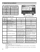

38
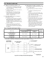
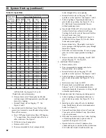
Table 8: Ignition Module Terminal Cross-Reference
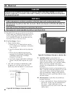
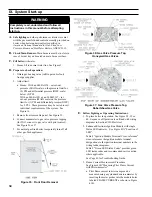
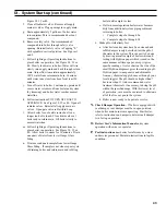
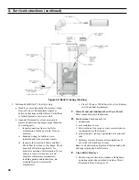
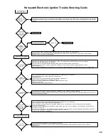
Figure 41A: Location of LED
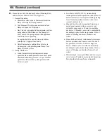
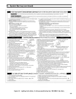
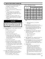
TABLE 8: Green LED Status Codes
Ignition Module
Terminal Designation
Wiring Ladder Diagram
Terminal Number
MV
1
MV/PV
2
PV
3
GND
4
24V (GND)
5
24V
6
SPARK
9
Green LED
Flash
Code
a
Indicates
Next System Action
Recommended Service Action
OFF
No “Call for Heat”
N/A
None
Flash Fast
Power up - internal check
N/A
None
Heartbeat
Normal startup - ignition sequence
started (including prepurge)
N/A
None
4 Seconds ON
then “x” flashes
Device in run mode.
“x” = flame current to the nearest µA.
N/A
None
2
5 minute Retry Delay
- Pilot flame not detected during trial
for ignition
Initiate new trial for ignition after
retry delay completed.
If system fails to light on next trial for
ignition check gas supply, pilot burner,
spark and flame sense wiring, flame rod
contamination or out of position, burner
ground connection.
3
Recycle
- Flame failed during run
Initiate new trial for ignition. Flash
code will remain through the igni
-
tion trial until flame is proved.
If system fails to light on next trial for igni-
tion, check gas supply, pilot burner, flame
sense wiring, contamination of flame rod,
burner ground connection.
4
Flame sensed out of sequence
If situation self corrects within 10
seconds, control returns to normal
sequence. If flame out of sequence
remains longer than 10 seconds,
control will resume normal opera
-
tion 1 hour after error is corrected.
Check for pilot flame. Replace gas valve
if pilot flame present. If no pilot flame,
cycle “Call for Heat.” If error repeats,
replace control.
6
Control Internal Error
Control remains in wait mode.
When the fault corrects, control
resumes normal operation.
Cycle “Call for Heat”. If error repeats,
replace control.
7
Flame rod shorted to ground
Control remains in wait mode.
When the fault corrects, control
resumes normal operation.
Check flame sense lead wire for damage
or shorting. Check that flame rod is
in proper position. Check flame rod
ceramic for cracks, damage or tracking.
8
Low secondary voltage supply- (be-
low 15.5 Vac)
Control remains in wait mode.
When the fault corrects, control
resumes normal operation.
Check transformer and AC line for proper
input voltage to the control. Check with
full system load on the transformer.
a
Flash Code Descriptions:
- Flash Fast: rapid blinking
- Heartbeat: Constant ½ second bright, ½ second dim cycles.
- 4 second solid on pulse followed by “x” 1 second flashes indicates flame current to the nearest µA. This is only available in
run mode.
- A single flash code number signifies that the LED flashes X times at 2Hz, remains off for two seconds, and then repeats the
sequence.
IX. System Start-up (continued)
Содержание INDEPENDENCE
Страница 4: ...4 Figure 1 Dimensional Drawing...
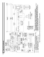
Страница 28: ...28 Figure 32 Wiring Diagrams Steam Intermittent Ignition EI Probe Low Water Cutoff VIII Electrical continued...
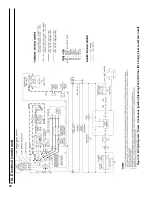
Страница 32: ...32 Figure 34 Wiring Diagrams Steam Intermittent Ignition EI Float Low Water Cutoff VIII Electrical continued...
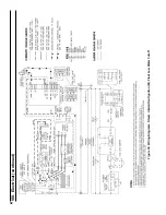
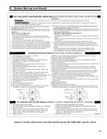
Страница 35: ...35 Figure 38 Lighting Instructions Continuous Ignition System 7000 ERHC Gas Valve IX System Start up continued...
Страница 56: ...56 Manifold and 1 Main Burners XI Repair Parts continued...
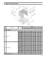
Страница 62: ...62 XI Repair Parts continued...
Страница 64: ...64 XI Repair Parts continued...
Страница 72: ...72 U S Boiler Company Inc P O Box 3020 Lancaster PA 17604 1 888 432 8887 www usboiler net...