11
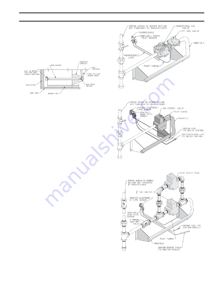
Figure 12: Pilot and Gas Piping, Intermittent
Ignition (EI) (IN3I through IN11 Only)
Figure 11: Pilot and Gas Piping, Continuous Ignition
(Standing Pilot) (IN10 through IN12 Only)
Figure 13: Pilot and Gas Piping, Intermittent
Ignition (EI) (IN12 Only)
8. Install black plastic rings into 1-3/32 inch diameter
holes located below upper louvers of front
removable door.
9. Install front removable door by engaging upper side
edges of panel with side receiving flanges, sliding
up and under top panel flange - seating front door
fully - then sliding down to engage bottom flange
behind lower front tie bar.
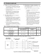
Figure 10: Combustion Chamber
G.
Install Pilot/Burner Assembly
(shipped in Gas
Controls Carton). See Figure 10.
1. Remove jacket front removable door.
a. Remove burner access panel located above
burners.
b. Install Pilot/Burner Assembly where noted on
gas manifold.
i.
Insert rear of burner in burner tray slot.
ii.
Position burner over the orifice.
NOTE: The burner to the right may need to
be lifted from the orifice to install pilot/
burner assembly. Reinstall lifted burner
over the orifice.
c. Reinstall burner access panel.
H.
Install Gas Valve
on main gas burner assembly (if not
factory assembled). See Figure 11, 12 or 13.
1. Connect gas valve to manifold.
2. Connect pilot tubing from pilot burner to gas valve
pilot tapping.
3. Continuous Ignition (standing pilot): connect
thermocouple to gas valve.
I.
Install Blocked Vent Switch
with sheet metal screws.
1. Models IN3I - IN9I. Install on rear flange of canopy.
See Figure 14.
2. Models IN10 - IN12. Install on right side of draft
hood. See Figure 15. Reset switch must face away
from draft hood relief opening.
3. Attach black 18-2 harness to Blocked Vent Switch
terminals. Use end with two fully insulated
disconnects.
4. Secure harness to right side jacket panel with clamp.
5. Insert harness through ¾ inch hole in right side
jacket panel. Secure with strain relief bushing.
II. Knocked-Down Boiler Assembly (continued)
Содержание INDEPENDENCE
Страница 4: ...4 Figure 1 Dimensional Drawing...
Страница 28: ...28 Figure 32 Wiring Diagrams Steam Intermittent Ignition EI Probe Low Water Cutoff VIII Electrical continued...
Страница 32: ...32 Figure 34 Wiring Diagrams Steam Intermittent Ignition EI Float Low Water Cutoff VIII Electrical continued...
Страница 35: ...35 Figure 38 Lighting Instructions Continuous Ignition System 7000 ERHC Gas Valve IX System Start up continued...
Страница 56: ...56 Manifold and 1 Main Burners XI Repair Parts continued...
Страница 62: ...62 XI Repair Parts continued...
Страница 64: ...64 XI Repair Parts continued...
Страница 72: ...72 U S Boiler Company Inc P O Box 3020 Lancaster PA 17604 1 888 432 8887 www usboiler net...


