background image

USER GUIDE

 Control Operation - Service 6

u-line.com

SAFETY • INSTALLATION & INTEGRATION • OPERATING INSTRUCTIONS • MAINTENANCE • 

SERVICE

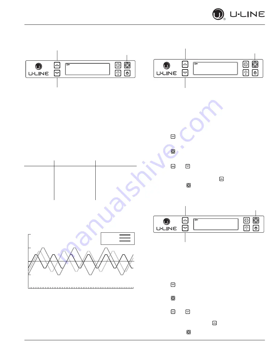
Differentials

(DO NOT MAKE AN ADJUSTMENT TO THIS WITHOUT 
CONTACTING TECH LINE: 800-779-2955)

Differentials are used to determine the maximum variation 
from set point and have a range of 0 through 10. The 
table below shows the effect of differentials on cooling 
cycles with a set point of 45°F (7°C).

NOTE: Air temperature does not reflect product 
temperatures.

The graph below shows a unit’s cooling cycle over time 
with various differentials.

Evap Fan (Not Used)

The Evap Fan option in the service menu allows servicers 
to change the Evaporator Fan runtime (in minutes) from 0 
to 98 and OFF cycle time 0 to 98.

To access Evap Fan

1. Press   to select “Evap Fan”.

2. Press .

3. Press   and   to scroll through available settings.

To exit the Evap Fan menu, press   to select “Return to 
Menu” and press   to confirm.

Mullion (Not Used)

The Mullion (MULL) option in the service menu allows 
servicers to change the ON/OFF time in minutes of the 
MULL heater (DWR only) from 0 to 98.

To access Mullion

1. Press   to select “MULL”.

2. Press .

3. Press   and   to scroll through available settings.

To exit the MULL menu, press   to select “Return to 

Menu” and press   to confirm.

Differential

Cycle Start °F (°C) Cycle End °F (°C)

0

45° (7°)

43° (6°)

1

46° (8°)

43° (6°)

2

47° (8°)

41° (5°)

3

48° (9°)

41° (5°)

4

49° (10°)

39° (4°)

5

50° (10°)

37° (3°)

Up

Select

Down

RETURN TO MENU

DIFFERENTIALS

ZONE = 1°F

Can be displayed in Celsius

p'LɞHUHQWLDO
p'LɞHUHQWLDO
p'LɞHUHQWLDO

Up

Select

Down

RETURN TO MENU

EVAP FAN 

EVAP FAN ON = 1

EVAP FAN OFF = 60

Up

Select

Down

RETURN TO MENU

MULL

MULL ON = 5

MULL OFF = 30

Содержание U-3018CLR

Страница 1: ...ER GUIDE SERVICE MANUAL SAFETY INSTALLATION INTEGRATION OPERATING INSTRUCTIONS MAINTENANCE SERVICE Modular 3000 Series 3018CLR 18 Clear Ice Machine RIGHT PRODUCT RIGHT PLACE RIGHT TEMPERATURE SINCE 19...

Страница 2: ...p Bracket General Installation Integrated Grille Plinth Dimensions Grille Plinth Installation Door Stop Door Adjust Operating Instructions First Use Control Operation Ice Sabbath Mode Airflow and Prod...

Страница 3: ...decades and is proud to have the opportunity to ship to you PRODUCT INFORMATION Looking for additional information on your product User Guides Spec Sheets CAD Drawings Compliance Documentation and Pr...

Страница 4: ...sted throughout this guide SAFETY ALERT DEFINITIONS Throughout this guide are safety items labeled with a Danger Warning or Caution based on the risk type DANGER Danger means that failure to follow th...

Страница 5: ...freezer take off the doors and leave shelves in place so children may not easily climb inside If the unit is being removed from service for disposal check and obey all federal state and local regulati...

Страница 6: ...F 10 C and 100 F 38 C Higher ambient temperatures may reduce the unit s ability to reach low temperatures and or reduce ice production on applicable models For best performance keep the unit out of di...

Страница 7: ...use an extension cord to connect power to the unit Always keep your working area dry NOTICE Electrical installation must observe all state and local codes This unit requires connection to a grounded...

Страница 8: ...k Although not required you may choose to increase the overall cutout width for ease of installation The Modular 3000 Series units are engineered with a variety of adjustment features to help ensure a...

Страница 9: ...ions 1 u line com SAFETY INSTALLATION INTEGRATION OPERATING INSTRUCTIONS MAINTENANCE SERVICE Product Dimensions Not Including Handle 24 610 mm 33 11 16 to 34 11 16 856 mm to 881 mm 17 3 4 450 mm 3 5 8...

Страница 10: ...out Dimensions in each unit s Installation Guide Each door can be opened individually one at a time without interference However to ensure unobstructed door swing opening both doors at the same time 1...

Страница 11: ...ction WARNING Connect to potable water supply only CAUTION Review obey and understand the local plumbing codes before you install your unit Connect to the cold water supply The water pressure should b...

Страница 12: ...an the solenoid valve Normal operation creates some vibration A water supply line contacting an internal component or cabinet wall can cause excessive noise during operation or damage to the line 4 On...

Страница 13: ...property damage NOTICE Drain can NOT be located directly below the unit Unit has a solid base that will not allow the unit to drain below itself There is a possibility that hose connections may have l...

Страница 14: ...to install a P60 drain pump into your unit see DRAIN PUMP section in the User Manual See below for typical installations requiring a drain pump NOTICE The maximum lift for the P60 drain pump is 10 fe...

Страница 15: ...e U Line Clear Ice Machine and is UL recognized only for use on the U Line Clear Ice Machine U Line Corporation assumes no warranties or responsibility whether express or implied if the P60 00 drain p...

Страница 16: ...space between leveling leg and pump Note Slide clamp on hose end before installing hose Do not tighten clamp until pump and hoses have been installed 4 Install the 3 hoses and hose clamps to the pump...

Страница 17: ...nt tube to kink bend or be obstructed in any way CAUTION Vent tube must be straight and parallel to insulated tubes Do not over tighten the plastic tie wraps Over tightening can pinch vent tube closed...

Страница 18: ...m drill bit drill 3 pilot holes 5 8 16 mm deep into bottom of counter top Use the anti tip bracket as a template 4 Install 3 8x5 8 screws into the plate using a 2 Phillips head screwdriver SIDE MOUNT...

Страница 19: ...1 8 3 mm less than the opening s rear height Shorten the unit height in the front by adjusting the front legs This allows the unit to be gently tipped into the opening Adjust the front legs to level...

Страница 20: ...r stain your grille plinth strip base fascia panel to match your surrounding furniture Finish front back and edges to prevent warping Carefully follow the manufacturer s recommendations for finish app...

Страница 21: ...th strip base fascia rail with screw heads in base of unit 2 Push grille plinth strip base fascia rails towards the center of the unit and set rails over screw head 3 Slide grille plinth strip base fa...

Страница 22: ...approximately 90 2 Remove hinge cover by lifting top and bottom of hinge cover and sliding the cover inwards to remove from hinge 3 Once cover is removed slide hinge pin into hole as shown Pin should...

Страница 23: ...e that it is firmly in contact with the cabinet Also make sure the door gasket is not pinched on the hinge side of the door CAUTION Do not attempt to use the door to raise or pivot your unit This woul...

Страница 24: ...ove caps from screw heads on opposite side 2 on top and 2 on bottom Using 2 Phillips bit remove the 4 underlying screws Reinstall the screws and caps on the opposite side 5 Partially install screw 1 i...

Страница 25: ...g the first two to three hours of operation to avoid possible dirt or scale that may dislodge from the water line When plugged in the unit will begin operating under the factory default setting Follow...

Страница 26: ...4 Hours 4 To exit press or simply wait for the menu to time out CUSTOMER MENU The 3000 Series of U Line undercounter refrigeration appliances contains a feature rich customer menu The Customer Menu al...

Страница 27: ...turn to the Customer Menu press and select Return to Menu Energy Saver Mode Energy Saver mode reduces overall energy consumption by reducing the amount of ice stored in the bin along with decreasing t...

Страница 28: ...ow and Off To select a new tone level enter the Sound Level Menu from the Customer Menu 1 Press or to select the current sound level 2 Press The current setting will begin to flash 3 Press or to selec...

Страница 29: ...s complete After 3 hours in Silent Mode normal ice production will continue NOTE Silent Mode will not silence any alerts To initiate Silent Mode enter Silent Mode Menu from within the Customer Menu To...

Страница 30: ...RUCTIONS MAINTENANCE SERVICE Help To access the Help Menu select Help from the Customer Menu Press or to scroll through available information To return to the Customer Menu press to select Return to M...

Страница 31: ...maintain an ice bridge of approximately 1 16 to 1 8 1 6 mm to 3 2 mm under normal conditions resulting in a dimple of approximately 1 4 to 1 2 6 4 mm to 12 7 mm in depth A fuller cube with less of a d...

Страница 32: ...UST Adjust ice thickness as follows 1 Press and hold for 5 seconds to enter the Customer Menu 2 Press to select Ice Adjust 3 Press The selection will begin to flash 4 Press to make the ice thicker or...

Страница 33: ...Star K certified U Line units at www star k org To prepare the unit for the Sabbath 1 Press and hold the until the unit turns off 2 No new ice will form when the unit is off but previously made ice wi...

Страница 34: ...GRATION OPERATING INSTRUCTIONS MAINTENANCE SERVICE Airflow and Product Loading NOTICE The unit requires proper airflow to perform at its highest efficiency Do not block the front grille at any time or...

Страница 35: ...ning in the stainless steel to become blurred Rust not cleaned up promptly can penetrate the surface of the stainless steel and complete removal of the rust may not be possible Integrated Models To cl...

Страница 36: ...se anything to force ice from the evaporator Damage may result 1 Switch the ice maker off and allow any ice to melt off of the evaporator 2 Remove all ice from the storage bin 3 Remove evaporator cove...

Страница 37: ...r flows over the evaporator assembly ice mold Initially the water flow may not be uniform causing uneven sized cubes or water to spill into the ice storage bin This is a normal situation that will cor...

Страница 38: ...ecessary Depending on environmental conditions more or less frequent cleaning may be necessary WARNING Disconnect electric current to the unit before cleaning the condenser NOTICE DO NOT use any type...

Страница 39: ...ter is removed from the lines 7 The door must remain open to prevent formation of mold and mildew Open door a minimum of 2 50 mm to provide the necessary ventilation WINTERIZATION If the unit will be...

Страница 40: ...description of the normal operating sounds they make NOTE Your product may not contain all the components listed Compressor The compressor makes a hum or pulsing sound that may be heard when it operat...

Страница 41: ...nd free of any dirt or lint buildup Water in Bin Ensure the unit is plugged in Check if the drain is restricted Ensure drain is free of foreign debris and hose is not kinked or twisted Hear Running Wa...

Страница 42: ...ranty arising by operation of law U Line will not be responsible for any consequential or incidental damages arising from the breach of these warranties or any other warranty whether express implied o...

Страница 43: ...T RELAY EMBRACO COMPRESSOR GREEN W YELLOW GROUND PINK LIGHT BLUE HOT WHITE 115V DARK BLUE 220 240V WHITE 115V DARK BLUE 220 240V PURPLE PUMP BLACK 115V BROWN 220 240V FAN 115 VOLT PLUG CONTROL BOARD B...

Страница 44: ...ment of a part the servicer is authorized to replace the part in question The part that caused the damage must be returned to U Line in its entirety The part must be clearly labeled with the serial nu...

Страница 45: ...dashes 12 represents the production month In most cases warranty status can be verified by the production date information within the serial number Alternatively a Proof of Purchase or equivalent may...

Страница 46: ...31 00 20 Hi temp thermistor 80 54070 00 21 Hinge covers 2 pcs 80 54001 00 22 Hinge mounting hole covers 80 54024 00 23 Hinges 2 w screws and covers 80 54013 00 24 Hot gas valve and coil 80 54169 00 25...

Страница 47: ...rts will be shipped at no charge after U Line confirms warranty status Please provide the model serial number part number and part description Some parts will require color or voltage information If U...

Страница 48: ...ge Lower than normal Warm near room temperature Hot Warm Warm Extremely cold near inlet Outlet below room temperature Lower than normal Partial Restriction Somewhat lower than normal vacuum Warm near...

Страница 49: ...atic wrist strap that is grounded to an electrical ground or grounded water pipe Handle circuit boards carefully and avoid touching components To measure the start winding resistance measure across th...

Страница 50: ...is some diagnostic tips and as always if additional help is required please contact the U Line Corp Customer Care Facility at 1 800 779 2547 for assistance NORMAL OPERATING SOUNDS All models incorpor...

Страница 51: ...e level unit if needed Low Ice Production Dirty evaporator dirty condenser faulty bin thermistor Clean the evaporator using U Line cleaner clean the condenser coil if needed check bin thermistor readi...

Страница 52: ...flow chart below to help diagnose the issue Before beginning it is important to first verify the unit is not simply set to sabbath mode Check Voltage At Wall Outlet Verify Voltage At Main Control Volt...

Страница 53: ...MONITORS THE STATE OF DC OUTPUTS evaS FRQGHQVHU IDQV DQG OLJKWLQJ R Oow med high OFFSETS ARE USED TO ADJUST OR CORRECT THERMISTOR READINGS CORRECTED VALUES MAY BE VIEWED THROUGH THE CUSTOMER MENU SELF...

Страница 54: ...olution No Comm Unit lost communication to the display Unplug the communication cable from the user interface Check the black to red conductors looking for 5 VDC If voltage is present replace the user...

Страница 55: ...hile all available relays are displayed only a portion are used NOTE The Cond Condenser Fan will switch state with the compressor relay however the condenser fan is actually powered through a DC outpu...

Страница 56: ...te of each available input To access Input Status 1 Press to select Input Status 2 Press 3 Press and to scroll through available information To exit the Input Status menu press to select Return to Men...

Страница 57: ...and to scroll through available thermistors To change offsets 4 Press the selected thermistor will begin to flash 5 Press or to modify offset value 6 Press to confirm setting To exit the Offset menu p...

Страница 58: ...d OFF cycle time 0 to 98 To access Evap Fan 1 Press to select Evap Fan 2 Press 3 Press and to scroll through available settings To exit the Evap Fan menu press to select Return to Menu and press to co...

Страница 59: ...lows the units model information to be modified Changing the units model completely reprograms available zones relay assignments DC output assignments etc To access Re Select Model 1 Press to select R...

Страница 60: ...Delay 2 Press To change fan delay 3 Press to select either Fan Delay On or Fan Delay Off and press The chosen option will begin to flash 4 Press or to change settings 5 Press to confirm To exit Fan D...

Страница 61: ...This unit has three thermistors Thermistor one Ice Bin Located along the right hand side wall of the ice bin It is used to maintain the ice level in the bin Thermistor two Condensor Line Out Located o...

Страница 62: ...k OHMs 5 Thermistor Resistance Data Type 2 Temp F Temp C Nominal Resistance OHMS 22 30 177000 13 25 130370 4 20 97070 5 15 72929 14 10 55330 23 5 42315 32 0 32650 41 5 25388 50 10 19900 59 15 15708 68...

Страница 63: ...USER GUIDE Defrost 1 u line com SAFETY INSTALLATION INTEGRATION OPERATING INSTRUCTIONS MAINTENANCE SERVICE Defrost These models have no defrost options...

Отзывы: