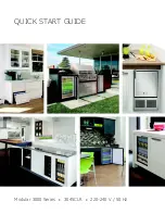
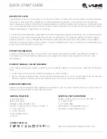

QUICK START GUIDE
8
u-line.com
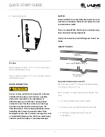
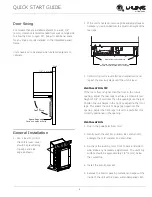
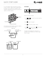
Door Swing
For models that are installed adjacent to a wall, 1/4"
(6 mm) clearance is recommended from wall on hinge side
to allow the door to open 90°. Allow for additional space
for any knobs or pulls installed on the integrated panel/
frame.
Units have a zero clearance when installed adjacent to
cabinets.
General Installation
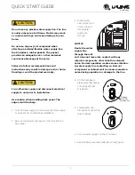
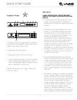
1. Use a level to confirm
the unit is level. Level
should be placed along
top edge and side
edge as shown.
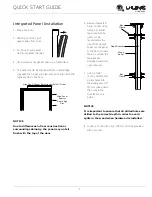
2. If the unit is not level, remove grille and adjust legs as
necessary. Use included tool to adjust the height of the
rear legs.
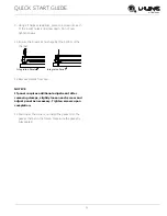
3. Confirm the unit is level after each adjustment and
repeat the previous steps until the unit is level.
INSTALLATION TIP
If the room floor is higher than the floor in the cutout
opening, adjust the rear legs to achieve a total unit rear
height of 1/8" (3 mm) less than the opening’s rear height.
Shorten the unit height in the front by adjusting the front
legs. This allows the unit to be gently tipped into the
opening. Adjust the front legs to level the unit after it is
correctly positioned in the opening.
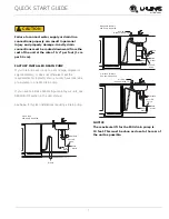
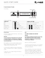
INSTALLATION
1. Plug in the power/electrical cord.
2. Gently push the unit into position. Be careful not to
entangle the cord or water and drain lines.
3. Re-check the leveling, from front to back and side to
side. Make any necessary adjustments. The unit’s top
surface should be approximately 1/8" (3 mm) below
the countertop.
4. Install the anti-tip bracket.
5. Remove the interior packing material and wipe out the
inside of the unit with a clean, water-dampened cloth.
Wall
90°
Door Swing
Space Required
For any Knobs or Pulls
1/4" (6 mm)
2
1
Rotate Clockwise to raise rear leg.
Rotate Counter-Clockwise to lower leg.
Rotate Front Legs to Adjust